One of the biggest design considerations for an injection molded part is wall thickness. Generally, the thickest wall section of the molded part or runner system is going to determine the amount of cooling time required during the injection molding process. Since cooling time often represents the longest part of the injection molding process, not optimizing wall sections on parts can have significant long term cost implications.
We are going to take an example part and run a few flow and cooling simulations to predict what changing the wall section can do for cooling time. Note that it is possible for the runner system to have the thickest wall section. Therefore it’s also important to design a runner system that is large enough to fill a part efficiently but also small enough to optimize cycle time but not cause excessive pressure during fill.
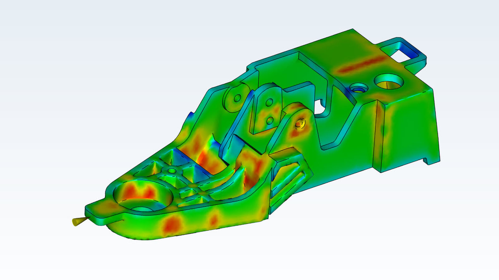
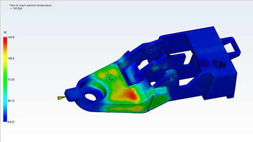
The images below are flow simulations done on a part with a thick wall section. The colors represent the time it takes to remove 80% of the heat from the plastic. You can see in the results that the thick wall section is the biggest factor in cooling (red area). The cooling time for the thinner wall sections is at the low end on the scale when compared to the thick wall sections. Because of the thick wall section, the time to reach the ejection temperature is just over 140 seconds.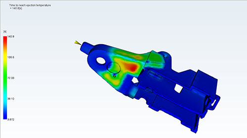
The excessively thick areas of the part can cause other issues as well. To provide enough plastic to those areas, the gate will need to be larger. These areas will also need longer holding time in an attempt to avoid sink marks. This may eliminate the ability to automatically shear gates during the molding process, which may require manual cutting or automation equipment. Gates should be large enough to fill the part but small enough to freeze off in the right amount of time to make a complete part. You can see that the wall thickness of the part is a factor in choosing the type of gate as well.
In the image below, we have cored out the part and made the wall section as even as possible throughout. Coring out the part reduced the simulated time to reach ejection temperature from 140 seconds down to 26 seconds. Looking closely at the images, you can see some red areas that are cooling the slowest. Given the part geometry can be further modified, we can continue to optimize the wall thickness of the part.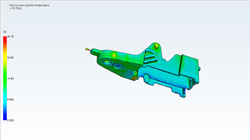
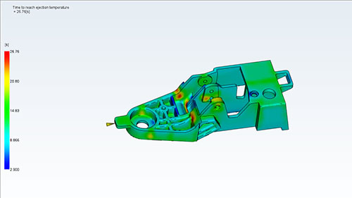
Having consistent cooling throughout the part also helps to create even shrinking as the part cools. We want to part to cool as consistently as possible. This avoids undesirable warping of the part during cooling or after the part is ejected. Looking at the previous images, you’ll notice a difference in the consistency of color throughout the part.
In the first images, the amount of time it takes the large wall section to cool makes the other areas (blue in color) insignificant in comparison. Whereas in the second set of images, the part has some consistency in color variation. This is showing that the part is cooling at roughly the same rate. This is known as cooling time variance and should be designed to be as low as possible.
As you can see, having uniform wall thickness is important for designing a part for the injection molding process. We can optimize not only the cooling time but also fill, pack, and hold. This will make the part run as fast as possible while still maintaining quality. All of which saves on machine time, reducing ongoing costs associated with injection molded parts.
This post is part of our Designing for Injection Molding series. Check out more here.