INJECTION MOLDING
quick guide
Just over 100 years ago, the first Injection Molding press was created. The machine was simple but effective, and it started an industry that will forever change manufacturing. The injection molding process, when compared to other manufacturing methods, can often be more cost-effective and still exhibit a wide array of advanced material properties.
Designing your part for Injection Molding is critical to realize those advantages. You’ll also find that designing your part correctly will yield a balance of optimum performance and cost-effectiveness. The following information is an overview of the most important elements for injection molded parts and represents both general injection mold design best practices and decades of personal experience. For the full guide, check out the links below.
Let Basilius assist with your Injection Molding Project. Request a quote today to get started.
Material Choice
With dozens of manufacturers, hybrid materials, additives, and fillers available on the market, there are thousands of material options. This can be overwhelming. However, in reality, there are only a handful of materials that make up the bulk of the market. It’s easier to understand if you start with some core material characteristics.
Plastics (in this context) are nothing more than groups of polymer chains. These are microscopic groups of repeating atoms (think of it like DNA). The composition of these polymer chains varies between different types of plastics. That variation has a significant impact on the properties of the plastic and your part. Two plastics could look the same but exhibit drastic differences in performance.
For the sake of design, we just want to understand the general characteristics of plastics. We will look at the major characteristics of plastics and some design considerations. There are two major categories of plastics; Thermosets and Thermoplastics.
Thermosets
Thermoplastics
Amorphous
- ABS
- Acrylic
- Polycarbonate
- PVC
Semi-Crystalline
Semi-Crystalline plastics have random sections of crystalline structures. In other words, they are a hybrid of amorphous and a completely crystalline structure. They make great bearing surfaces, living hinges, and provide good chemical resistance. The downside is that they shrink and warp more than Amorphous plastics. Here are some of the most common types:
- Acetal
- Nylon
- PBT
- HDPE
- LDPE
- PET
- Polypropylene
Semi-Crystalline
It’s common to have variations of the material listed above using additives and fillers. In the most simple applications, the injection molder can change the color of the material by using color additives. Color can be changed at the molding machine or from the material manufacturer. More advanced materials or “engineered materials” are created by material manufacturers. For example, polycarbonate can have varying levels of fiber-glass added by the manufacturer. The material will still come in the form of pellets to the injection molder but can yield significantly higher strength with the added glass fibers. Other fillers like talc and carbon fiber are also common.
Fillers and additives can change other material properties. These can include UV protectants, antioxidants, antistatics, antimicrobials, lubricants, and so on. Keep in mind that they are application specific. Instead of trying to understand everything about materials, start with what your part requires and focus on that. You can also leverage the knowledge of an injection molder, like Basilius, who has a network for material suppliers. Not only are these suppliers developing new materials constantly, but they also have a deep understanding of applications.
Selecting a Parting Line
One of the first considerations of an injection mold design is selecting the parting line, or where the two halves of the mold come together. For some applications, there’s an obvious choice; but in others, the best option may not be so clear.
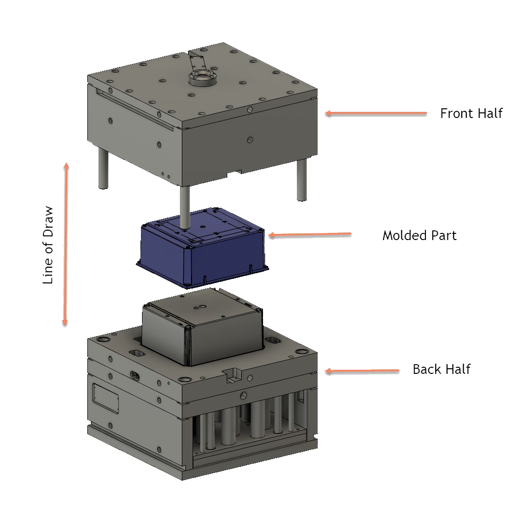
The first step is deciding which direction the line of draw (the direction the mold opens) will be for the mold. In Figure 1 below, you can see how the mold is in two halves, the line of draw, and how the two halves would come together at the parting line.
You should be looking at how to make a simple but effective mold—a mold that generates the part the way you want it but avoids adding cam actions and lifters if they are not necessary. Based on the image from above, you wouldn’t make the line of draw from the side of the part. Doing so would produce a large undercut on the inside of the box and make the mold unnecessarily complicated.
When selecting a parting line, you also want to decide on the A and B sides of the part. It’s common to have show surfaces (the side that will be seen) on the A-side of the tooling; but there is a second consideration. As the mold opens, the parts need to stay on the B-side or ejection side of the mold. Making sure the part transfers to the B-side ensures consistent functionality of the mold during production. Luckily, we can use some material characteristics to our advantage.
Since plastic shrinks as it cools, it will shrink onto surfaces. You can use the shrinking to make sure the part stays on one side of the mold as it opens. The B-side of the mold will often have more complicated and protruding features. These features allow the plastic to cool onto that side and away from the A-side. At the same time, allowing the plastic to stick and shrink too hard will make the part eject forcefully or get stuck in the mold.
Adding Draft
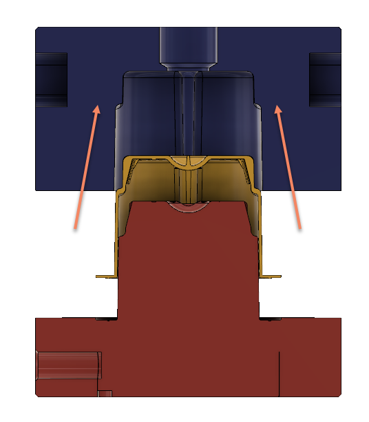
An injection mold design needs to ensure the part comes out of the mold without damage or too much resistance. To avoid these issues, you want to angle the walls of the part from the parting line (drafting). Generally speaking, there should not be any surface of the part that is exactly 90 degrees to the line of draw on the mold. Not drafting a part can cause defects like drag marks and create difficult ejection. In Figure 2, the A-side tooling is colored blue, the B-side is red, and the part is yellow. Notice the small amount of draft (referenced by the angled lines) that allows the part (yellow) to break free from the tooling block (red).
The amount of draft you should apply to the part depends on the application. The general rule is to have at least one degree for every inch of depth. Below is a list of different design considerations where you want to add to the amount of draft.
Features of the A-Side of the Tooling
Amount of Texture
Deep or Thin Ribs
Small Features
Small features like holes can make a part stick during ejection or cause cracking. Even the smallest features should have some draft applied.
Design Note: It’s uncommon but possible to have no draft on a particular feature. In these cases, it’s usually one area of the part that needs to mate with another component and cannot have draft. Having no draft is not recommended. Even ¼ degree can make a difference.
Avoiding Thick Areas
An injection molded part needs to come out of the mold without damage or too much resistance. To avoid these issues, you want to angle the walls of the part from the parting line (drafting). Generally speaking, there should not be any surface of the part that is exactly 90 degrees to the line of draw on the mold. Not drafting a part can cause defects like drag marks and create difficult ejection. In the image below, the A-side tooling is colored blue, the B-side is red, and the part is yellow. Notice the small amount of draft (referenced by the angled lines) that allows the part (yellow) to break free from the tooling block (red).
The amount of draft you should apply to the part depends on the application. The general rule is to have at least one degree for every inch of depth. Below is a list of different design considerations where you want to add to the amount of draft.
Design Note: Having to “add plastic” to a molded part means removing steel from the mold. Machining away material in the mold is much cheaper and easier than welding and machining. We call this being “steel safe.” It’s common to stay steel safe on critical dimensions, test run the mold, check dimensions, and then remove steel to finalize that dimension.
Coring & Ribbing
To avoid thick sections of a part, you can add coring and ribbing. These features reduce cycle time, reduce part weight, and could make the part stronger. Designing these features into the B-side of the part is common and is the best practice. These features can help pull the part to the B-side or ejection side of the mold; they would then be on the non-show side of the part. However, it’s possible to have them on the A-side of the tooling as well.
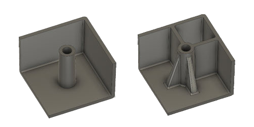
Figure 3 shows a perfect example of coring a part. Since this part required one large wall section, you can remove large sections of material without sacrificing strength. Think of this in terms of other common structural components like tubing and I-beams. Because of the way forces are applied to these components, removing the material doesn’t change its structural integrity. The image on the left is cored out, and the image on the right is not. Using simulation software, we were able to predict that the part without coring required double the cooling time. The added time in the molding machine increases the cost of the parts, and over time, those numbers can be huge.
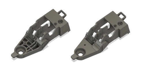
From Figure 3, you can see that the coring is not just a large section of removed material. Instead, it’s more a webbing of wall sections (known as ribs). Adding ribs is a great way to add significant strength to a part without affecting cycle time. Ribs can also reduce the amount of material that is used in the part. Figure 4 shows a boss before and after adding support ribs. Since these ribs are thin, they do not increase cooling time, but they do add strength. Notice that the ribbing towards the corner of the part is also creating coring (right). It’s common to have bosses like this on the corner of a part. When possible, it’s best to allow enough room to have coring completely surrounding the boss. This helps to avoid thick wall sections that could show through in the form of part defects (like sink marks from the material shrinking more in thick areas) on the outside show surface of a part. Don’t forget draft!
Uniform Wall Thickness
Keeping all major wall sections throughout a part as consistent as possible is key to plastic injection molding. Doing so keeps material flow in the cavity consistent and makes for even cooling. The previous images from the coring and ribbing section are good examples of this. Most injection molding materials do not react well to flowing through large differences in thickness. Inconsistent wall thickness can cause pressure spikes, material degradation, too high of differential pressure across the part, and poor process control. The plastic also cools at different rates when you have varying wall thickness.
The mold surface is cooling the part from the outside surfaces inward. This means that the middle area of a wall section will cool last. Having areas of the part cooling at different rates can cause warping issues (covered later).
Exceptions
Adding ribbing to a part can generate a thicker wall section in a small area where the rib meets the base. As discussed above, thick wall sections can cause sink issues because the material is shrinking as it cools. To avoid sinking, design ribs slightly smaller to reduce the wall section at the connection point. Taking the same part from above, you can see the thick areas that could create sink marks on the show side of the part (shown on the Figure 5 left image). In Figure 5 right image, you can see that the ribbing is thinner than the main wall section. The radii are also slightly smaller to reduce the potential for a section that is too thick.
Adding RADii
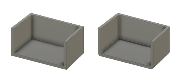
Not only are radii more visually appealing, they also help plastic flow more smoothly and reduce the likelihood of fractures during plastic injection molding. When designing radii, keep in mind the uniform wall thickness best practice. Figure 6 shows a simplified and sectioned cover. Adding radii helps make sure plastic flows through the part consistently, keeps the wall sections even, makes the part more visually appealing, and avoids potential cracking/fracture points.
Surface Finish
Building injection molds requires several different pieces of equipment. To create molding surfaces, they may be CNC machined, ground, EDM’d, turned, and so on. Each of these manufacturing processes will generate different surface textures. These textures (tooling marks) may be acceptable for non-show surfaces, but in many cases, tooling marks need to be smoothed out or textured. Creating a texture not only makes the surface of the molded part consistent, but it also has implications on part design.
Basic Surface Finishes
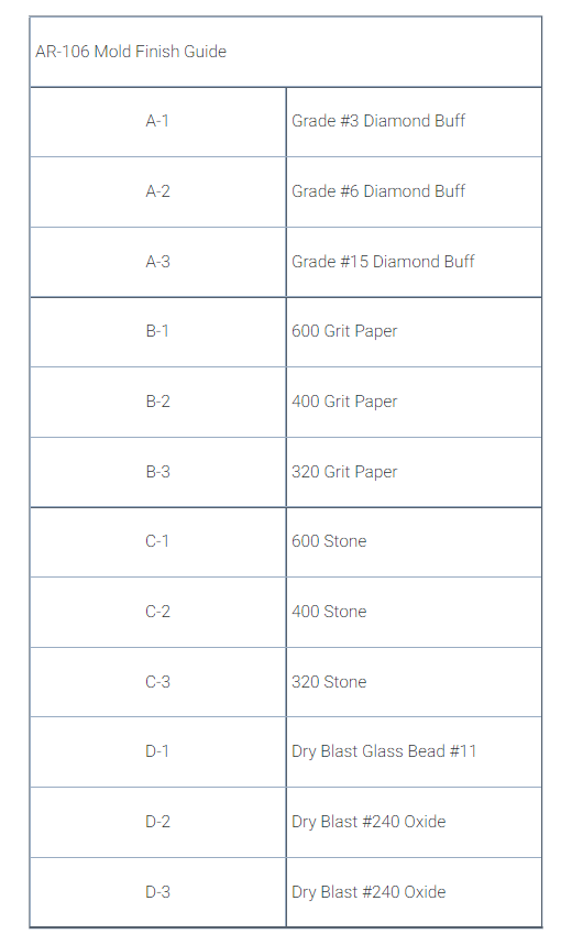
The surface of the plastic part is a direct translation of the surface of the mold. For example, to mold a clear lens, the mold will have a highly polished or mirrored surface. In these cases, even a fingerprint or a hairline scratch can show through on the molded part. Figure 7 is a surface finish guide created by the Plastic Industry Association for use during plastic injection molding.
As you can imagine, going up the scale to the “A” surface finish gets more time consuming, and therefore, raises tooling cost. Starting at C-3, each stage on this scale builds on the one before it. That is, you would not start with diamond polish on a surface with tooling marks. You would work your way up the scale through the different finishes.
EDM Texture
Sinker EDMs create sandpaper-like texture as a normal part of their operation. In other words, the finish resembles sandpaper, not the finish created by sandpaper. Since EDMs use electricity to remove material, the roughness of the texture is directly related to the intensity of the settings on the EDM.
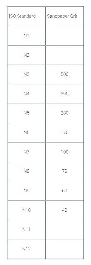
Surface roughness, in general, can be a complicated subject with several different standards. For the sake of understanding an EDM finish, we’ve put together a basic guide Figure 8 referencing the equivalent sandpaper—meaning the roughness of the sandpaper itself and not the finish the sandpaper would leave.
Note that this is a general guideline and is for reference only. The point here is to help you understand the look and feel of an EDM finish, not to establish an accurate means of specifying a surface finish.
Other Textures
Design Considerations
Hinges & Clip Actions
Living Hinges
Living hinges are common for molding components like container caps. Since the cap consists of a base and a lid, a living hinge is the connection point between the two. Not only does this make the cap easy to use for the consumer, but it also saves on manufacturing costs and assembly time. Making a long-lasting living hinge comes down to proper design and material choice.
Living hinges are weak points in the part where the two halves of a part come together. This weak area needs to be thin enough to be flexible but thick enough to handle hundreds or thousands of movements. Figure 9 are a few cut-away images of living hinges. As discussed earlier, it’s best to start with the design steel safe and then make adjustments after molding.
Clips
Like hinges, clip actions require careful attention to design and material selection. Design starts with understanding the function of the clip action. For clips that require repeated function, it’s important to make sure the clip (or surrounding areas) don’t fatigue over time. A good example of this is a lid for a container. The clip action needs to hold the lid closed, release with ease when needed, but also last through hundreds or thousands of releases. On the other hand, one-time-use clips can be designed with more rigid and interlocking features. A good example is a case for a consumer product. Once assembled, the parts need to stay permanently together or even resist impact without coming apart. In this scenario, it’s better to have the clip action interlock hard, making the assembly slightly harder but nearly impossible to break apart. Here are a few considerations when designing a clip action.
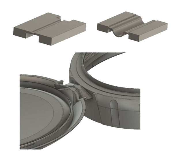
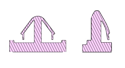
Clip Movement
Since a clip action needs to flex and return into a locked position, the amount of movement required to complete the clip action is important. Figure 10 showcases a few cut-aways of parts that snap into sheet metal holes. Notice the length of the arm and the depth of the clip action. The arm is long enough to allow flexing without permanent distortion. The clip area is deep enough to lock into the mating part, but not so big that it overextends the arm and causes permanent distortion. As with other features, staying steel safe, testing, and modifying the mold with steel removal is the best practice.
Mold Design Concerns
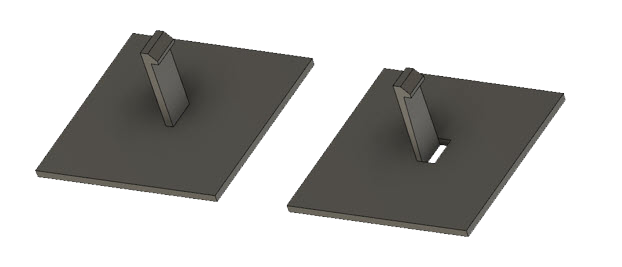
The examples above have the benefit of being molded directly in the line of draw of the mold. In other cases, like Figure 11, the clip action may need to be in the middle of the part, generating an undercut. If the design allows, you can avoid the added complication of actions by designing a hole through the part. The hole allows one half of the tooling to protrude through the part to produce the undercut.
Whether you have a new part, are updating an existing one, or changing the manufacturing process, it’s important to design for manufacturing. The short and long-term cost/timing implications can be large if you’re not designing a component with the manufacturing process in mind. In this guide, you’ve learned about everything from the injection molding process, to design tips for various part details.
We hope that you are better informed and can use this knowledge to optimize your components for plastic injection molding. If you’re designing a plastic part, we highly recommend getting an injection molder like Basilius involved as early as possible. With Basilius, you can leverage years of experience, a network of suppliers, in-house injection mold design, mold building, and injection molding to make your product come to life quickly and efficiently.
Designing for injection molding
Your complete guide to injection mold design