Edge gates are widely used 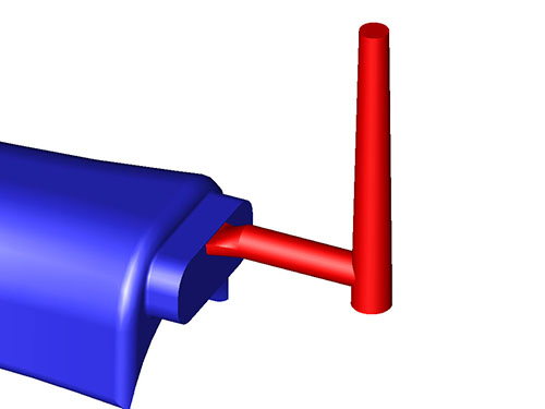 for their simplicity and effectiveness in the injection molding process. They are easy to produce when building a mold and are easily modified if needed. They are also ideal for filling larger parts or parts where thicker wall sections could not be avoided. An edge gate can have a larger cross–sectional area compared to other gates. This allows more plastic to flow into the mold and the ability to have longer hold times because of the longer gate freeze.
For simplicity, we grouped edge gates with fan gates and tab gates. The image below shows an edge gate where the circular shape of the runner tapers into the rectangular shape of the gate. In the case of the fan gate, the shape would still be rectangular but would be wider than the width of the runner. The widening of the gate into a fan can help with plastic flow, dimensional stability, and may avoid some cosmetic issues.
Tab gates resemble edge gates but are a mostly consistent thickness for a short distance leading into the molded part. These gates are usually used on flat or thin parts to reduce shear stress. Since the first section of high shear created by the thin wall section is in the gate, the shear stress is more likely to be contained in the gate. The high shear area is then trimmed off after molding.
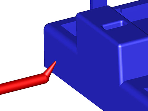 Tunnel gates or sub gates are machined below the parting line so that as the part is ejected the gate will be trimmed automatically. This style of gate is common for injection molding for small parts, high cavitation molds, or where gates need to be trimmed automatically.
The limitation of edge gates is the maximum cross-sectional area. Having too large of a tunnel gate can cause cracking or cosmetic issues due to the automatic shearing. Using a small gate to fill a large part can lead to excessive shear heating and difficulties in filling the part.
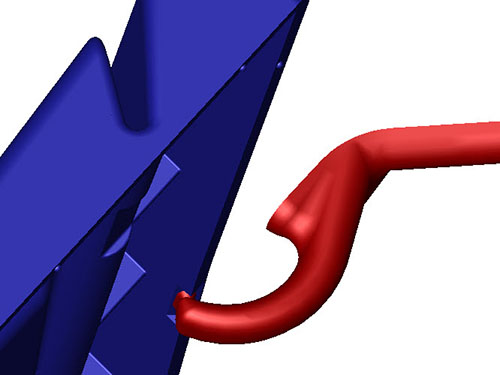 Much like a tunnel gate, the cashew gate is machined below the parting line and is automatically sheared during ejection. This style of gate is used to get the injection location behind or below a show surface. Cashew gates often have the same limitations as tunnel gates in terms of size.
The challenge with cashew gates is that removing the gate during ejection requires the plastic to pull out around an arc. Because of this, there’s a chance the gate may break off. Removable gate inserts are typically added so that an operator can quickly remove the broken plastic without major intervention.
Diaphragm gates are used when a part has a large open 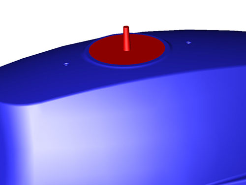 diameter in the middle of the part and even plastic flow is desired. Having even plastic flow helps to ensure that, when cooling, the part shrinks as consistently as possible. The diaphragm gate also allows a large amount of plastic to flow into the cavity.
The image shows a part we molded at Basilius with a diaphragm gate. Typically this style of gate is used on open-ended cylindrical parts. In this case, design limitations and the desire to have even fill made the diaphragm gate the best option. The red area in the image is the gate and was sheared off in a secondary operation.
Hot runner feed systems 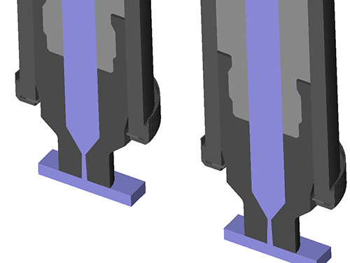 offer many advantages over cold runner systems. This is detailed more here. Hot runner systems are designed so that the molding material is kept molten between the molding machine barrel and the part (In some cases, there are short cold runner systems added after the hot runner). At that point, there are two main types of gates used.
The thermal gate functions much like a normal gate where the material is injected into a cavity and material pressure is held until enough cooling occurs. The advantage here is not having the runner system leading up to the gate. Material is saved and slightly better process control is established. This gate design can leave gate vestige because the gate area is broken away from the hot runner tip during mold opening.
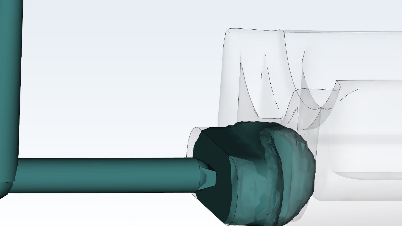
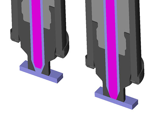 The valve gated hot runner system provides the same advantages of the hot runner thermal gate but adds another level of control. In this design, there is a movable pin inside the hot runner tip assembly. When back (left side of the image below), molten plastic can flow into the cavity. When forward (right side of the image below), plastic flow is shut off. This provides the ultimate control of a runner feed system, larger gate sizes, and less gate vestige.
Gate design is a critical component of the injection molding design process. Accessing the variables like part/mold design, material selection, and production intentions are important considerations when deciding what gate design is right for the job. We’ve built hundreds of molds over the years at each one using one of these designs or even variations of them. We hope this serves as a core understanding or gating and what options are available.