Like many industries, injection molding and tool building have some key terminology. Being in the industry, we tend to use them as if everyone already knows what we mean. We hope to clarify the terminology here.
Molding machine and its parameters
- Automatic Mode – The molding machine cycles automatically without operator intervention.
- Semi-Automatic Mode – The molding machine runs one cycle and then requires action from an operator.
- Barrel / Screw – Where the material is heated by heater bands and shear heat from screw rotation to melt plastic before it’s injected into a mold. Barrel and screw assemblies are matched together and vary in size from machine to machine. This is what sets the maximum volume of plastic available during injection.
- Nozzle – The end of the barrel where plastic flows out and into the mold. Nozzle tips are often interchanged from job to job to match the material and mold.
- Tonnage – The size of the molding machine in reference to how much force it can apply when closing a mold. The closing pressure is used to resist injection pressure and seal the mold. Generally speaking, you need more tonnage to make bigger parts. Higher tonnage machines also have larger barrel and screw assemblies for larger part volume.
- Platens – The surfaces to mount a mold into the molding machine. One side is considered a moving side, back half, or ejection side, and the other side is the stationary side or front half.
- Daylight – Clearance between two platens of a press in the open position. The daylight dimension determines the maximum mold size a press can properly operate.
Injection Molds / Tooling
- Cavity / Cavitation – A cavity is the portion of the mold that creates the molded part. The number of cavities (Cavitation) is the number of parts that are created each time a mold opens.
- Clamp Force – The amount of pressure used to hold a mold closed during the injection molding process. This is usually referred to in tonnage and is a defining characteristic of the injection molding press size.
- Family Mold / Tool – A multi-cavity mold where there are at least two different parts in the same mold. Used to create an assembly, balance quantities of different parts, save of tooling cost, and save on piece price.
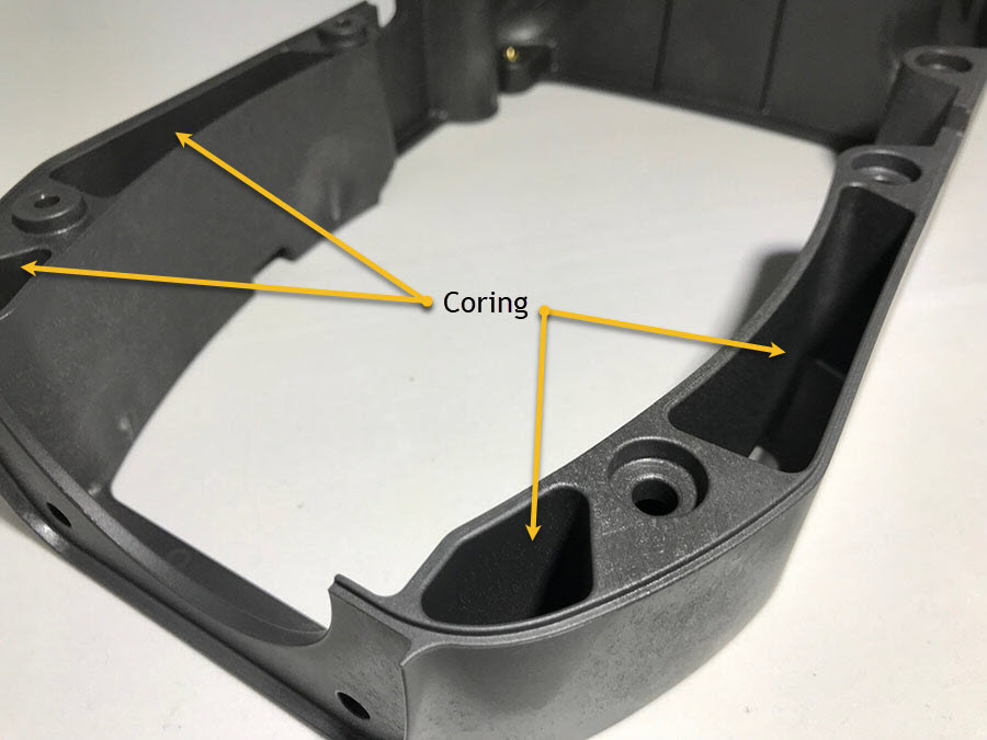
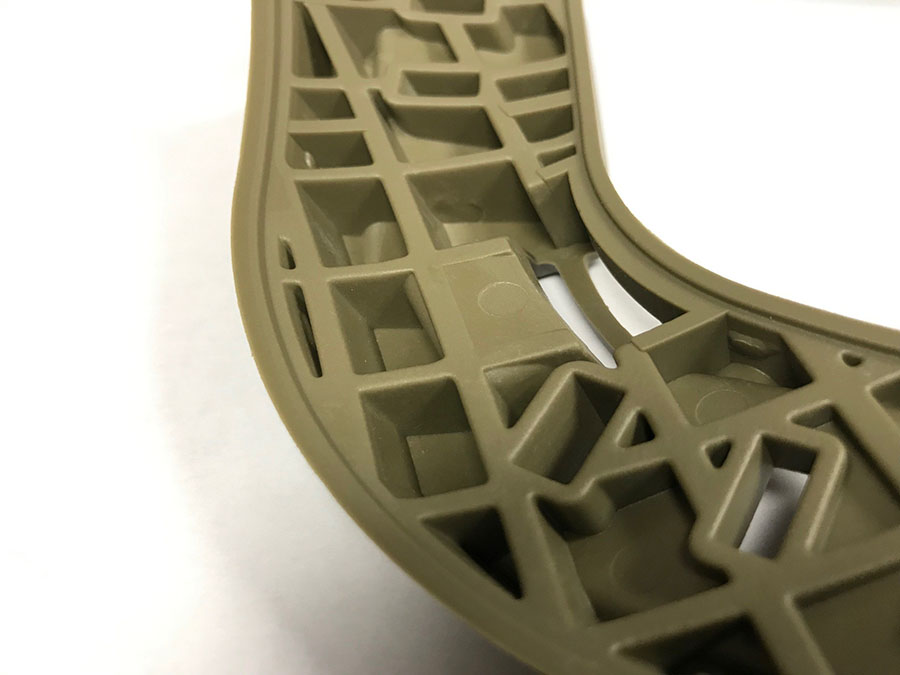
- Coring – Features of mold cavities that reduce the part thickness and optimize the strength of the part by eliminating excess plastic. You can imagine in the picture below how thick the plastic would be if indicated areas were not cored out. To Maintain uniform wall thickness there is additional coring on the opposite side of the part (not visible in image).
- Cycle – The time it takes for one full sequence of the molding operation to complete.
- Draft – The degree of angle of the walls of a plastic part. Angling the walls (drafting) allows easier removal of plastic parts from the cavities during the ejection process.
- Gate – The transition point where plastic flows from the runner into the cavity. Read more on gate design.
- Vent – As plastic flows into a mold the air needs to escape. Vents are located at various points in the cavity to allow air to flow out as plastic flows in.
- Cam / Slide Action – Moving components of the mold the create undercuts in a part. Check out this post to see cam actions.
- Parting Line– Where the two halves of the mold come together to create a part. This can be seen on a finished part as a small line in the plastic.
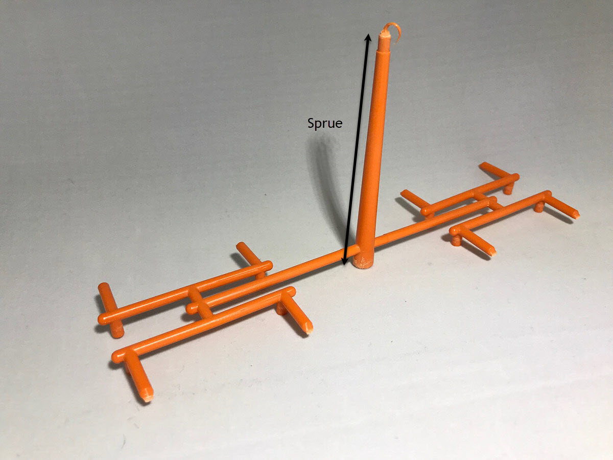
- Sprue / Sprue Bushing – The sprue is first area the plastic flows into from the molding machine barrel. The sprue bushing is the machined component that creates a plastic sprue. The image shows the sprue section of a feed system.
- Runner Systems – After molten material flows into the sprue it flows through a runner system to reach each cavity of the mold. The image below shows the different turns and joints that make up the runner section of a feed system. The end of the runner leads to the gate, which leads to the part. Notice the design of the runner is such that the distance from the beginning of the sprue to each part is the same. This is known as a balanced runner system.
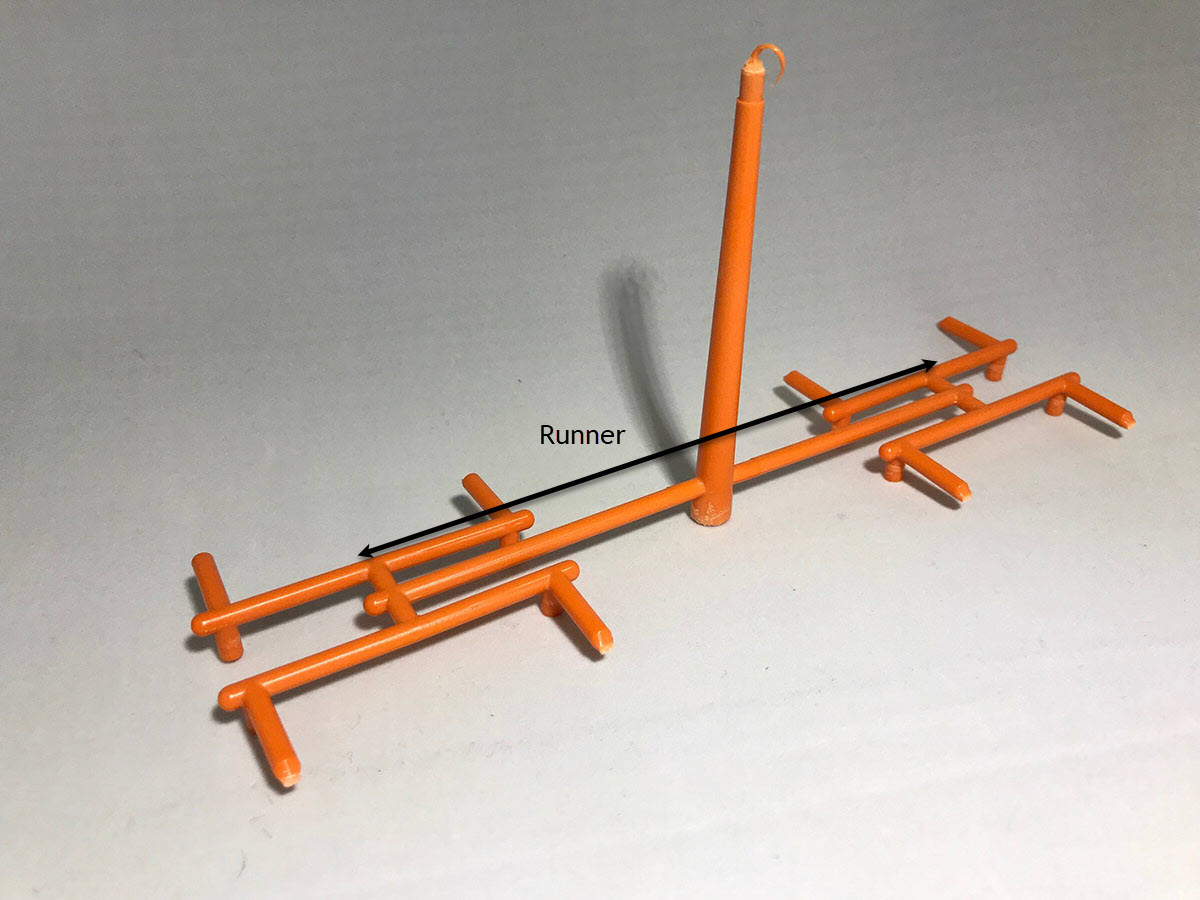
- Cold Runner – A runner system where the plastic flowing from the sprue is split as needed to fill the cavities but is not heated. The images above are an example of a cold runner.
- Hot Runner – The sprue and runners are heated in a manifold such that the material can flow through them in a molten state. This runner system may end up directly flowing into the cavity (creating no runner) or just short of one or a few cavities creating a small runner. This saves on wasted material or the need to recycle material. Read more about hot and cold runner systems.
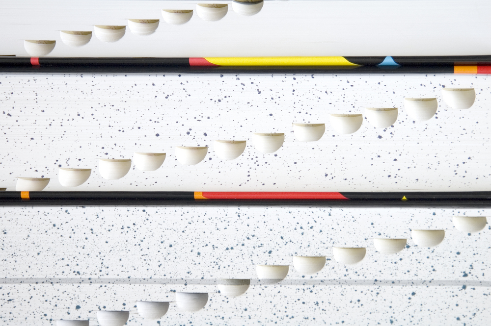
- Rib(s) / Ribbing – A reinforcing component of a plastic part. Ribs or ribbing also optimizes the use of plastic by creating thinner wall sections (lower cycle times and cost) without sacrificing significant part strength. The image shows several ribs that strengthen the part, optimize weight and uses less material.
Molding Materials
- Additives / Fillers – Molding materials may have several different additives to achieve certain material properties.
- Thermoplastic – A classification of plastics that, when heated, does not undergo a chemical change in composition. They can be used over and over. These are more common and include polyethylene (PE), polypropylene (PP), polystyrene (PS), and polyvinyl chloride (PVC).
- Thermoset – A classification of plastics that, when heated, undergo a chemical change in composition. Therefore, they are heated and formed once. An example is volcanized rubber.
- Amorphous Plastics – The molecular organization in a polymer in mostly disorganized. These plastics tend to have good impact resistance and dimensional stability. Examples include ABS, polycarbonate, and acrylic.
- Semi-Crystalline Plastics – The molecular organization in a polymer in mostly organized into a crystalline structure. These plastics tend to have good wear resistance and chemical resistance. Examples include: Polypropylene, polyethylene, and acetal.
- Melt Flow Index (MFR) – A measure of how easily a plastic flows at it’s melting point. The higher the MFR, the lower the viscosity. Note that comparing melt flow rates of materials in different classes (like polycarbonate and polypropylene) is not an accurate comparison as they have different melt points. The MFR of a material is best used when comparing materials in the same class.
Injection Molding
- Shrinkage – When a plastic component is molded it shrinks as it cools in the mold. The amount that it shrinks is determined by the material and molding parameters. This is usually expressed in the amount of shrinkage per inch. Because of this, a mold cavity is designed bigger than the finished part. As the part is cooled, a dimensionally correct part is created.
- Shot / Shot Size – The yield from one complete molding cycle. The shot size will be the total amount of plastic used which includes the runner and sprue.
- Defect – Check out this blog post for a full list of potential defects for injection molded parts as well as their remedies.
- Overmolding– The process of molding a polymer over a substrate. A substrate may not necessarily be another plastic. This process is used for creating ergonomic and cosmetic features but is certainly not limited to that. Check out this post for more information on overmolding.
- Insert Molding – The process of molding an insert (usually a small piece of threaded metal) directly into a plastic part. Generally, the inserts are loaded into a molding machine before the injection molding process. The insert is then molded directly in the part, creating a strong thread in a plastic part. Check out this post for more information on insert molding.