Designing For Molding: Insert & Overmolding

As custom molders, we see a lot of part designs requiring metal inserts and overmolding operations. Both of these types of molding involve the same process of loading something into a mold and injecting plastic into or over it to make one complete part.

When looking at this as a broad topic there’s almost no limit on what can be overmolded. Even components like electrical connectors, circuit boards, and medical tubing can be overmolded.

Insert Molding

Insert molding is a common way to achieve a rigid thread or other feature in a plastic part. This can avoid a complicated mold, unscrewing mechanisms, or heat staking, and other secondary operations. The inserts can be made of nearly any material however, brass, stainless steel, or coated ferrous metals are the most common. Here are a few examples of insert molded parts.

Insert Molded Part 2
Insert Molded Part 1
Insert Molded Part 3

Insert molding begins in the design phase of the mold build. There are two critical design aspects for properly designing an insert tooling design. The first is properly holding the insert, so it does not shift during the injection process. Second is designing so the mold properly shuts off (seals) against the insert. These two aspects make sure the insert is in the same location each time and that no flashing or extra plastic gets molded in the wrong areas. 

For example, to hold an internally threaded nut in place we can use a pin that protrudes from the tooling that the insert sits on. The series of images below show the force and support pin of an example mold we’ve built. The next image adds the insert reference, then the cavity side tooling and then the part reference.

Insert Load reference 1
Insert Load reference 2
Insert Load reference 3
Insert Load reference 4

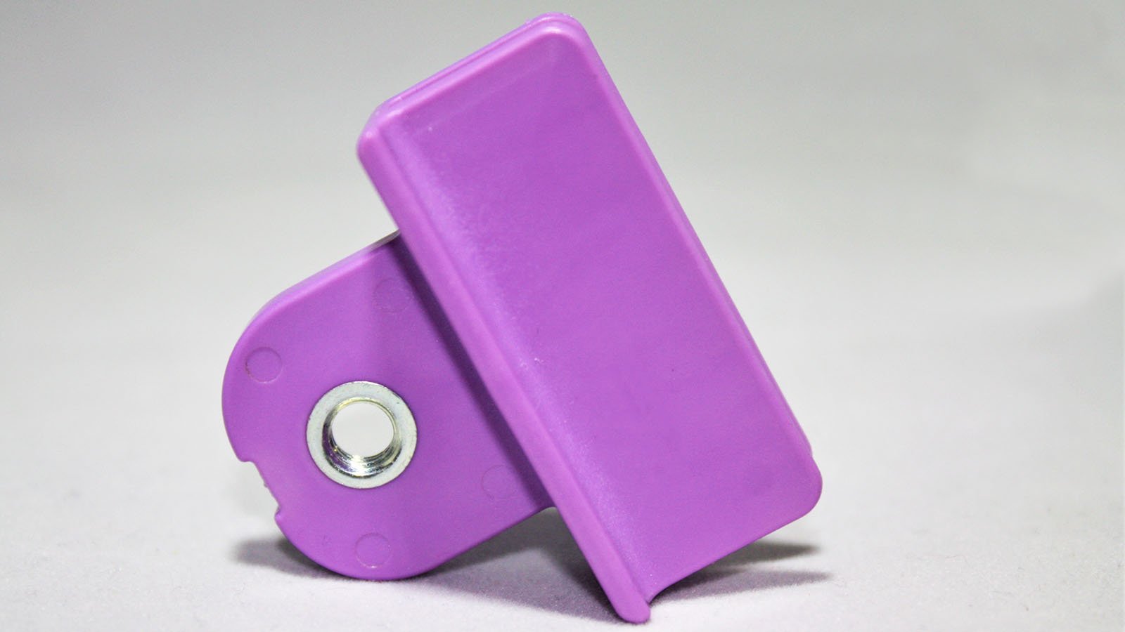
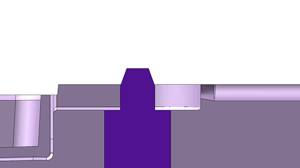
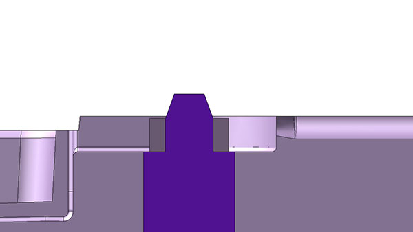
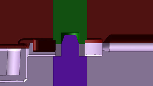
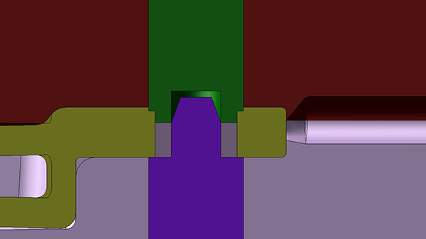
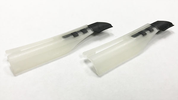
Depending on the accuracy of the insert, we may use a spring-loaded core pin on one side of the insert. This insert can then compress as the mold closes and allow for any small variations in the insert. In the example above we may take the green core pin and allow a small amount of float (up and down in the image). Some designs may not allow this if the injection pressure would push the pin back.

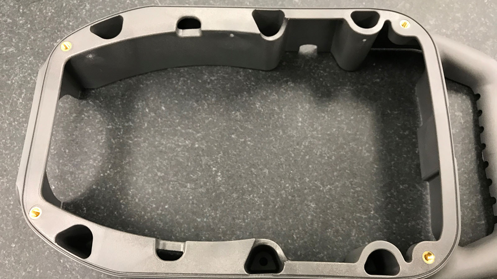
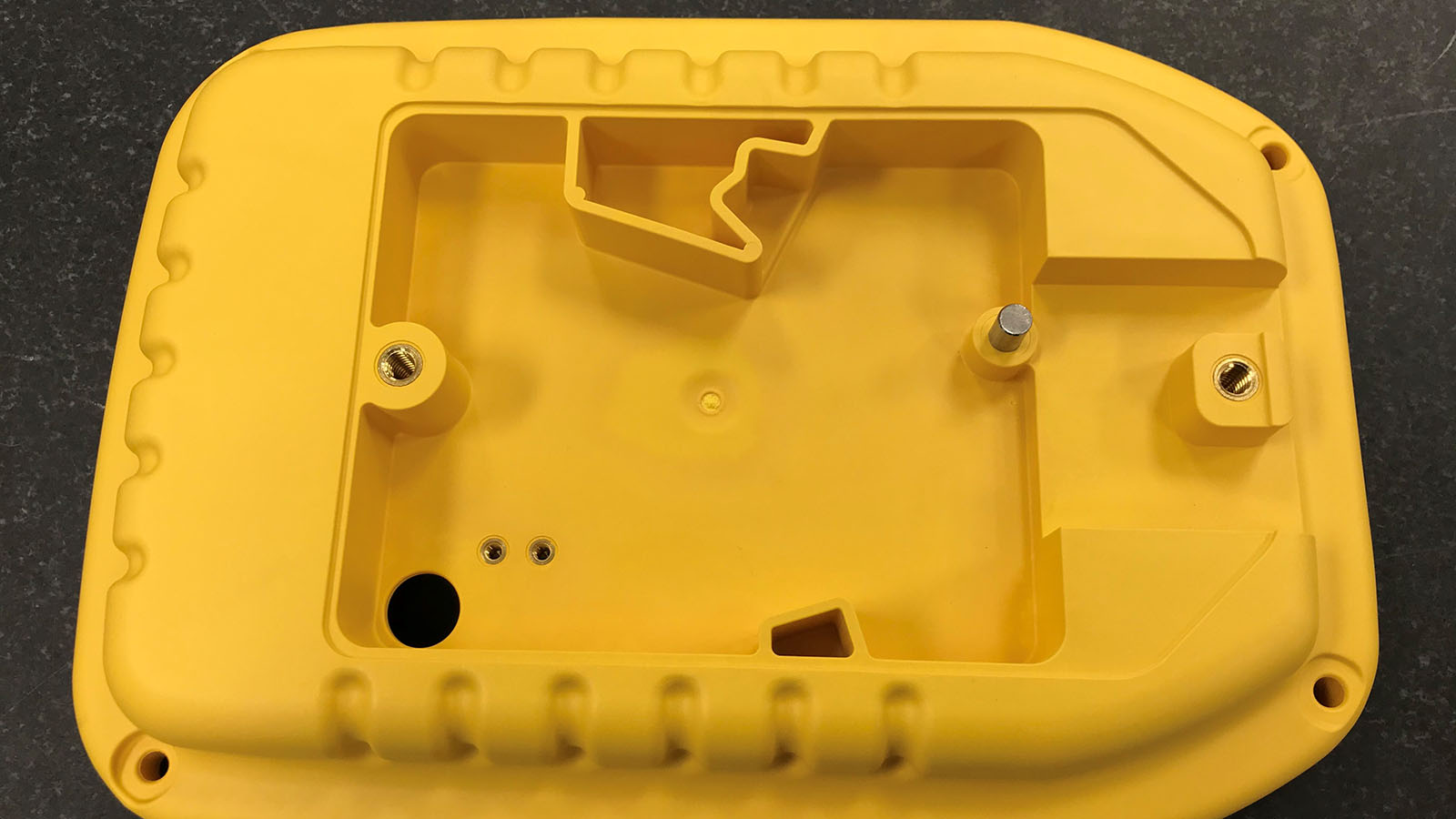
You’ll notice that the core pins (purple and green) core into each other. The taper of the purple pin is to allow a slight misalignment for operators or robotics when loading the inserts. When using robotics, we may also use docking pins for end of arm tooling to make sure the inserts are accurately located onto the pins in the mold. 

The injection molding process does not usually change for insert molding. We are still going to develop a process in the same manner, but there could be some other considerations. When we are adding one or many inserts into the mold, we may need to allow for extra cycle time whether the components are loaded by robotics or by hand.

Some cost implications for the insert molding are not only the insert itself but how it is loaded. For low volume applications, we can have a full-time operator. For automated systems, there could be some additional up-front costs associated with equipment like robotic tooling or orientation equipment like bowl feeders. This is another aspect of custom injection molding that is taken on a case by case basis. Like with choosing cavitation, we need to balance up-front investment with long term piece price savings. 

See more about Insert Molding….

Overmolding Plastic Substrates

Overmolding is typically molding a soft plastic over a rigid one. This may be for aesthetics, ergonomics, vibration resistance, or mechanical features. Unlike insert molding where we’re using a purchased component, we need to manufacture the substrate. This is typically going to be a harder type of plastic or one with a higher melting point than the overmold material. This is because we want to maintain the structural integrity of the substrate while we are molding another material over it. Here are a few examples of overmolded parts.

Overmolded Part 1
Overmolded Part 2

It’s possible to have one large mold run in a two-shot molding machine where both the substrate and the overmold are created at the same time. The substrate side of the mold may be rotated or robotics will transfer the substrate to the overmold cavity and transfer the finished part out of the molding machine. It’s also common to have two molds and run them at separate times and different machines. In this case, we will likely run a traditional process on a molding machine to create the substrates. Then we can either load the substrates into another molding machine by hand or with robotics for the overmolding operation. It’s common to use a vertical molding machine so the substrates stay in place as they are molded and can be easily accessed by an operator. 

Overmolding Other Components

It’s possible to add plastic around just about anything. The process is still the same where we load the substrate into the mold and build an injection molding process. Here are some images of unique overmolding applications. 

Overmolded Electrical Connector
 
Overmolded Medical Device
 

The applications for overmolding are seemingly endless. We can create features like threads, standoffs, and dowels by loading these inserts into a molding machine prior to molding process. Looking at the topic more broadly we can mold plastic over just about anything. From traditional applications like adding ergonomic grip points to more advanced electronics or medical devices, it’s all in the realm of possibility. These applications may even provide cost savings opportunities for component assemblies by avoiding secondary operations. 

This post is part of our Designing for Injection Molding series. Check out more here.

Basilius Logo
OUR LOCATION
CONTACT US