Designing for CNC Machining

CNC Machining

quick guide

Our CNC Machining guide will help you understand CNC processes, material options, finishes, offer cost savings opportunities, and provide some design tips. For the complete guide, follow the link below.

Designing for CNC Machining

Your complete guide to CNC Machining Design

What is CNC Machining?

CNC machining, or computerized numerical control machining, defines a broad range of material removal processes. Starting with the CAD (computer-aided design) data of a component, we will decide which CNC processes are best suited for the job. Using CAM (computer-aided machining) software, a machine operator/programmer pre-programs the various machines to produce the desired component. Common CNC processes include milling, turning, grinding, EDM, and deep hole drilling.

Milling

CNC milling is a process of removing material by using spindle (rotating) mounted tooling. Think of CNC milling as an advanced version of a conventional drill press, where an operator moves the rotating drill bit up and down manually and the part is stationary. A CNC mill will move both the rotating drill (tooling) and the component around to access different areas of the component. The different types of CNC milling processes are commonly defined by the tooling orientation (horizontal and vertical) and the number of axes

Vertical Milling

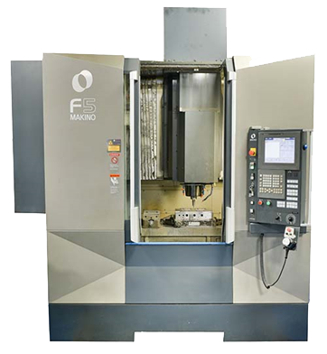
Like the drill press mentioned earlier, vertical milling operations have the tooling rotation running vertically (in the direction of gravity). A simple vertical CNC machine as seen in Figure 1 will have three axes where the tooling moves vertically; the table moves from the front to the back of the machine, as well as from side to side. These machines are common in many machine shops because they are cost-effective, simple to program, but still offer diverse capabilities.

Figure 1

Horizontal Milling

Horizontal milling machines have the same primary function as vertical machines— removing material from a component; however, in a horizontal milling machine the tooling spins horizontally. The two different machines can use the same type of tooling as well. Horizontal milling machines are often more expensive but are better suited for production machining. Horizontal milling machines will often have a fourth axis for part rotation and may also have a pallet changer (discussed later).

Multi-Axis Machines

The machines previously discussed are considered three-axis milling machines. Each additional axis represents an additional type of movement. Going beyond three and four-axis machines greatly expands the capability of a CNC machine. For example, a vertical milling machine may have an added axis which allows the component to rotate. This fixture is called a rotary table and is a common addition to three-axis machines. It is used to gain greater access to different areas of a component.

CNC Turning

Turning is a generic term used in the CNC industry to represent the use of a lathe. A lathe’s main function is to create round parts; however, as you will see, a lathe can have much more functionality. The lathe has a chuck that holds and spins the workpiece. The tooling is then moved around the workpiece to remove material. A simple lathe will have tooling that can move in two axes. In more advanced CNC turning equipment, more axes (directions of movement) are utilized to expand the functionality of the lathe. The added axes could be multiple chucks for different stages or the addition of milling type components to create more advanced features.

CNC Lathes

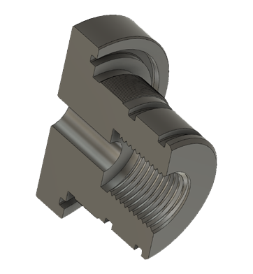
Like CNC milling, CNC lathes can use various types of tooling to create different features in round parts. These could be features like o-ring grooves, internal and external threads, face grooves, and so on. Lathes will also have a tailstock located opposite and in line with the chuck. The tailstock is used for holding a long workpiece or for completing various drilling functions. Figure 2 is a sectioned (cut in half) part that would be produced using a CNC lathe. Features include internal threads, external threads, outer diameter groove, inner diameter groove, and a face groove.

Figure 2

Live Tooling Lathes

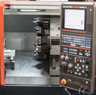
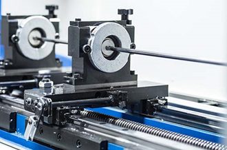
Live tooling lathes are a combination of a mill and a lathe. Like a lathe, there is a chuck holding and spinning the workpiece; however, the tooling is much more advanced. There are various tooling heads mounted to a turret. The turret allows for anything from standard lathe type tooling to mill type tooling. The added functionality makes it possible to dill and mill features off-center or perpendicular to the chuck rotation. Figure 3 is a photo of a live tooling lathe at Basilius.

Figure 3

Grinding

Grinding is a precision machining process that is used for accuracy and smooth surface finish. The different grinding operations all use grinding wheels in various ways. Grinding wheels are made of synthetic rock-like materials and they come in different shapes and sizes. They can also be custom formed (dressed) to create features like threads or small grooves. Compared to other processes, grinding is a slow but highly accurate process. Manual grinding is the most common, but CNC grinding is good for production environments and creating detailed features, like threads.

OD/ID Grinding

In OD or ID grinding, the workpiece is mounted into a rotating chuck (just like the lathe discussed earlier). Instead of tooling, there is a grinding wheel rotating at high rpm that engages the workpiece. The Grinding wheel is either CNC programmed or manually moved to engage the workpiece. OD (outer diameter) grinding removes material from the outside and face of a workpiece. ID (inner diameter) grinding removes material from the inside faces of a hole (bore).

Surface Grinding

Surface grinding is used for creating smooth and parallel surfaces. Like other grinding processes, material removal is slow but accurate. There are also various fixtures and devices for expanding the capabilities of a surface grinder. These capabilities may include grinding on different angles or creating custom features.

RAM EDM

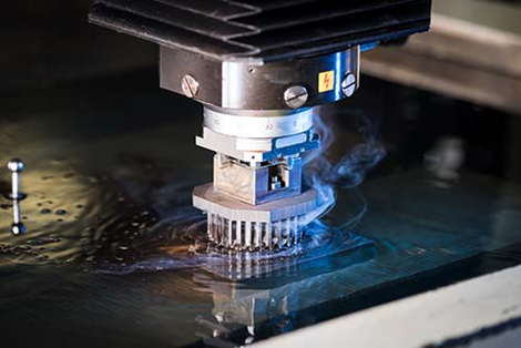
The RAM EDM, sometimes called a sinker, die sinker, or plunger, uses an electrode to produce the desired shape in the material via electrical current. First, a machinist will use 3D data of the desired part to design various electrodes around the part. The electrode is the negative (or opposite shape) of the desired shape in the material. Once the electrode is made, it is then placed into the RAM EDM. 

The image below shows an electrode mounted inside of a RAM EDM machine. After the electrode is placed into the RAM EDM, a dielectric oil surrounds the material and electrode. The oil is a critical component in the process as it serves as an ionizer for the current, flushes out the material being removed, and cools the electrode and workpiece.

Compared to a CNC Mill or Lathe, material is moved relatively slowly when common/soft steels are used. The advantages of the EDM compared to standard CNC machining are the ability to machine extremely hard materials with ease, produce features that are either difficult or impossible on other equipment, and produce an array of textures.

Figure 4

Wire EDM

Like the Ram EDM, the Wire EDM uses electrical current to remove material. The difference is that instead of using a machined electrode, a wire is used to cut a narrow channel through the material. Due to the corrosive nature of the EDM process, the wire is continuously moving so that it does not wear or break. The wire EDM is extremely accurate and used for making inserts, insert pockets, precision holes, tapered pockets, and small holes. Like the Ram, the wire can cut hardened material with ease.

Drilling EDM

Often called a “Hole Popper,” the drilling EDM functions using a spinning electrode rod to “drill” into materials. In the simplest form, workpieces are manually moved and the hole popper is manually aligned to location. However, much more advanced multi-axis CNC hole poppers have been developed. Since Wire EDMs require a starting hole, the hole popper is used in tandem where it creates a small starting hole that the wire EDM can work from as a starting point. Hole poppers can also create relatively accurate holes.

Deep Hole Drilling

One major aspect of any drilling operation is how deep a hole can be accurately drilled. The depth limit is typically measured relative to the diameter of the drill. This ratio is called the length to depth ratio. For example, a standard spiral drill is accurate to a length-to-diameter ratio of 5:1. If you were using that drill to produce a .500 diameter hole, a clean and accurate hole should be possible up to 2.5 inches deep. Going deeper is possible, but sticking to the 5:1 ratio is generally best in order to be safe, precise, and repeatable.

The most significant factors that limit the depth of any drilling operation are cooling and chip removal. In the case of the standard spiral drill—as hole depth increases, it becomes more difficult to get cooling to the cutting area and remove chips.

The unique design of the gun drill machine provides the ability to keep the cutting area cool and remove chips effectively at high L:D ratios. This is due to the high-pressure oil being directed right to the cutting surface. The oil is initially used for lubrication and cooling, but as the oil comes back out of the hole, it carries chips back out to keep the hole clean. The chips and oil are then collected in the base of the machine. The oil gets separated from the chips and recirculated through the process.

Another unique aspect of gun drilling is the way the drill is supported. In standard drilling operations, the drill is fixed to the spindle at one point on the drill. Therefore, the depth limit is set by the length of the drill bit. In gun drilling, the drill is supported at the beginning of the hole. During drilling, the drill moves through bearings and stays supported as the drill advances.

Figure 5

Honing

Honing is an abrasive type of material removal process. Typically used for internal holes (bores), the process is accurate and can provide a relatively high surface finish compared to CNC operations. At Basilius, we have a manual honing machine for creating reliable and smooth bores.

Materials

When designing a component for CNC machining, you want to consider strength requirements, chemical resistance, thermal stability, cost, and other such factors. Each material has different characteristics that can be found on material datasheets.

Plastics

In cases where plastic components are larger, more complicated in design, and order quantities are low, CNC machining can be a better choice than Injection Molding. It’s also possible to injection mold a component and then machine details, like threads or undercuts as a post-molding operation. Plastics are easier to CNC machine and do not wear on tooling (unlike metals). Common plastics for CNC machining:

Metals

Metals have diverse material properties which drive the performance characteristics of the final product. These various properties are great, but they should be balanced against raw material costs and machining cost. For example, if your part is specified to be stainless steel, you will find that there are several different grades of stainless steel that have large differences in both cost and material properties. Furthermore, some stainless steels are more cumbersome to cut than others, which means they will cost slightly more to CNC machine. Common metals for CNC machining:

Simplification Equals Savings

Contours

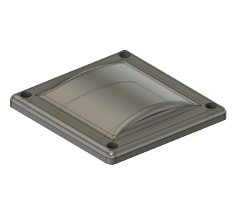
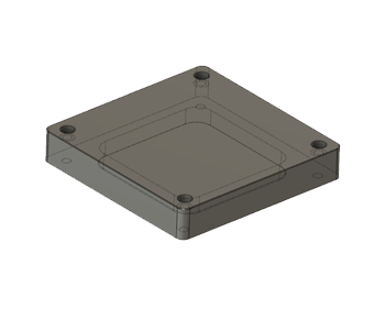
Contours are easy to create in CNC operations, but they require longer cycle times to produce. Unless a contour is needed for the part to function correctly, it is best to simplify the surfaces to save on machine time (part cost). Figure 6 shows the before and after of a part with and without a contour. Eliminating this contour could drastically reduce the cost of the component. You see the pocket on the underside of the part is simplified as well.

Figure 6 - Before
Figure 6 - After

Fillets / RADII / Chamfers

Fillets and radii are good design features for increasing strength and resisting cracking. They also make parts easier to handle and more aesthetically pleasing. Depending on the CNC process, fillets and radii may be inevitable; but in other cases, they may cause unnecessary complications. As an example, since milling operations use a rotating bit, inside corner radii are inevitable. The image below shows an example part with an inside corner radius.
Figure 7

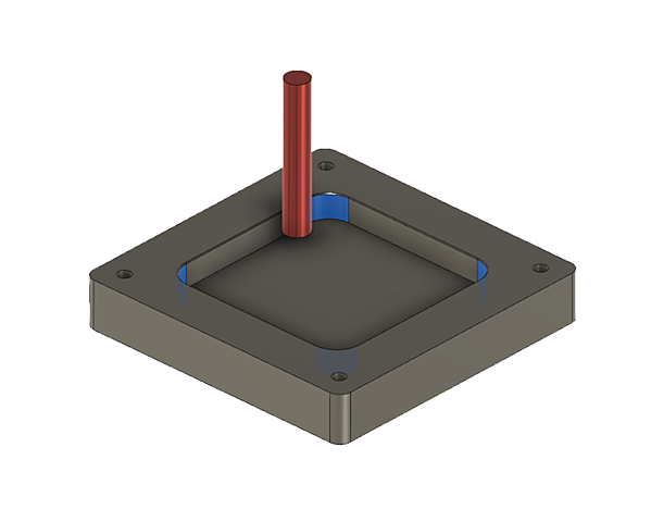
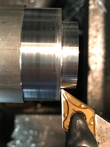
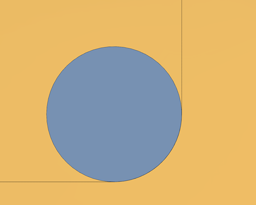
Figure 8 shows a common tooling insert for a lathe (gold color). Nearly all of these types of inserts have a rounded (radiused) end. The radius helps to cut away material more efficiently but will also generate a fillet on inside corners during CNC operations. 

If an inside corner for a turned component needs to be sharp, special “zero radius” tooling inserts will need to be used, which results in an added operation and tool setup. 

As a general rule, it is best to allow for fillets on turned parts in order to avoid the added operation. In a later section, we’ll show you some design tricks to help you avoid the added operation.

Figure 8

Limiting Setups

Setups are required any time a component needs to be put into a fixture or clamped into a machine. Each setup adds to machine time in the worst way. That is, the machine is on but not cutting material. Thus, moving parts around opens up room for error and wastes machine time. This is why multi-axis machines and pallet changers are such a huge advantage. Multi-axis machines can access more sides of a part, which reduces setups. Pallet changers allow an operator to set up the next set of parts while another set is cutting.

Depth & Size

The length to diameter ratio (L:D ratio) discussed earlier also applies to CNC milling. Designing small features that are hard to reach is likely to increase the cost of a component. An example is a thin and deep pocket. For CNC milling, deep and narrow areas require specialized tooling and are time-consuming to produce. They may even require the use of EDM equipment, requiring more setup time and an additional process.

Work Holding

When designing a part for CNC operations, it’s essential to think about work holding, or how a machine can grip a component in various ways to complete the CNC operations. Secondarily, if your component requires different set-ups, the machine operator will need to “locate” the part in the machine.

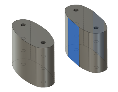
Operators need to be able to tell the machine where the part is. To do that, they need to locate something like a hole or a few details of the part. If a part is heavily contoured with no straight or parallel edges, it may be difficult or impossible to hold and locate. Below is a simple contoured part that could be easily CNC machined in a vertical mill from the top of the part. However, holding the part to get to the other bottom would be difficult for the part on the left. Adding two parallel faces (highlighted in blue on the right part) allows the part to be gripped in a vice and located in the machine. There are tricks like custom fixturing, but this adds extra set-up time that could otherwise be avoided.

Figure 9

Design Tips & Tricks

Eliminating a Corner Radius

As we mentioned earlier, the CNC milling operation automatically creates a radius on vertical inside corners. If your assembly requires a sharp corner, there are a few options available. The lower two corners in Figure 10 show the corners drilled out. The diameter of the hole is large enough that the vertical and horizontal walls are completely straight. The top two corners use a design feature that accomplishes a sharp corner with a slightly different design.

These features are designed around allowing a mating component to have a sharp corner. That is, something with sharp corners needs to fit into the pocket in Figure 10 above. If the mating component cannot be modified and the above design features are not possible, the corners can be EDM’d to a much smaller radius. As mentioned previously, this is an additional cost and set up that should be avoided
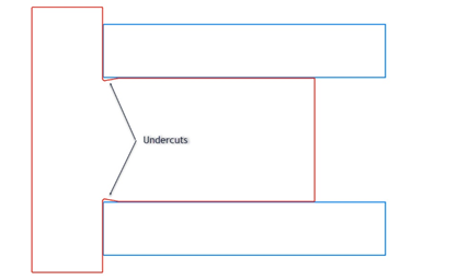
Figure 10

Turning Threads

For CNC turning threads, it is common to have the threads end into a face. The challenge is that when CNC turning threads, the tooling inserts cannot produce a thread that ends completely against a face. Meaning that a mating component could possibly bind and stop against the end of a thread rather than against the face. If the mating component cannot be modified, you can undercut the end of the thread to the root diameter of the thread in Figure 11.
Figure 11
When designing threads, it is also important to add a proper lead into the thread by using a simple chamfer (shown above). The small diameter of the chamfer should be smaller than the root diameter of the thread. This will prevent a burr; it also provides a nice lead-in for mating parts.

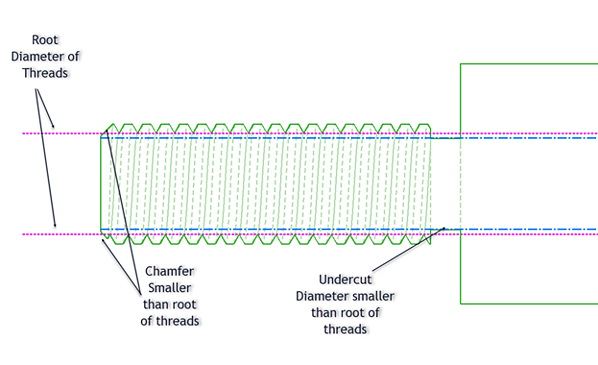
Zero Inside Radius on a Turned Component

Most lathe tooling has a radius for performance and chip removal, as discussed earlier. However, the radius may work against you if you need a sharp corner. You can design in a small undercut to make sure a mating component with a sharp corner can fully engage into the CNC turned part. Below is a common example of a pin (outlined in red) and a bushing (outlined in blue). The undercut on the pin allows the bushing to fully engage into the face of the pin without interference.
Figure 12

Non-Standard Fillets

When designing radii on a part, it is best practice to make the radius a non-standard value. That is, instead of having a .250 corner radius, make it slightly over (.260). Doing this ensures that CAM software generates the radius with cutting equipment, rather than allowing a tool to engage fully in a corner. In Figure 13-A, a half inch cutter is fully engaged into a corner with a ¼ inch fillet. The excess contact area causes chattering, which produces a rough finish and may cut the part slightly undersize. Figure 13-B is zoomed in more and shows the difference in contact area when a corner radius .260. The difference in design is small but makes the CNC process more robust. If a fillet is specified to be ¼ inch, an operator may program it to use a smaller tool to avoid full engagement. Doing so adds another setup and another operation (increasing cost slightly).

Figure 13-A
Figure13-B

Think Big

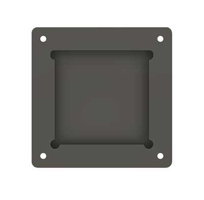
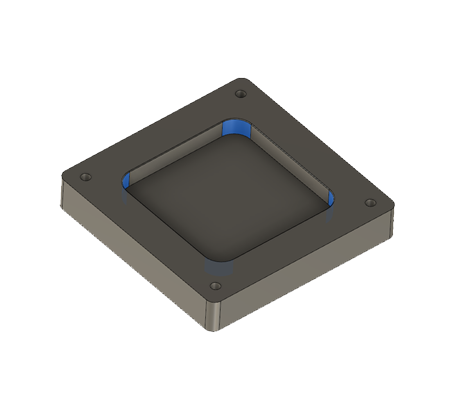
In general, smaller features take more time to make. For example, since a CNC milled pocket will generate an inside radius, it is better to have a radius at .260 than .100. In the example part shown below, the corner radii are highlighted in blue. The corner radius is .260 and therefore, can be produced by a half inch mill. That same tooling bit would likely be able to cut this entire part as well. If these radii were reduced to.135 , a 3/16 mill would be largest diameter tool able to produce the radius.

The smaller tooling may not serve much of a purpose beyond cutting the smaller radius. Therefore, the smaller radius would require the setup of another tool, a tool change, and additional programming. Keep in mind that design features like these are relative to the part design as a whole. If the part is small, then small features are unavoidable. The basic premise is that having lots of different design features that require several different types of tooling should be avoided when possible. It is also advantageous to keep sizes consistent throughout the part design.

Figure 14

Finishes

As Machined

Different CNC processes will leave different surfaces finishes. Leaving those surface finishes as they are is the most cost-effective and straightforward finish. The chart below shows some CNC operations and what range of surface finishes can be expected. Note that smoother surface finishes are possible without changing the operation but may require different tooling and extended machine time (higher cost).
Figure 15

Bead Blast

Bead blasting is a manual process of applying small glass beads under high pressure to the surface of a component. The beads cause a light texturizing that does not damage the component; instead, it creates a matte type texture. Depending on how detailed the part is and if it requires isolated texturing, bead blasting may or may not have an effect on component cost.

Polished Surfaces

Polishing surfaces can either be done by hand or by utilizing various types of machine polishing equipment. Basilius can provide hand polish surfaces to your specification or a barrel finish. The barrel finish type polishing is done by using a centrifugal finisher. The finishing equipment provides an isotropic finish, meaning that the surface will be consistent on all sides of the part.

Designing for CNC Machining

Your complete guide to CNC Machining Design