When polymers are heated, formed, and cooled, several things are happening on a molecular level. The molecules loosen up as they are heated, and during injection, they tend to align in the direction of flow. Depending on the type of material, additives, and process conditions, the amount of shrink will vary throughout the part as it cools. The differences in shrink throughout the part can cause it to warp. As it turns out, this is hard to predict.
First, we want to take a look at the different types of plastics and additives that will affect the shrink rate. There are two types of polymers, Amorphous and Semi-crystalline. For Amorphous polymers, the molecules are tangled and completely unorganized through heating and cooling. The flow of molten plastic during processing will cause the orientation of molecules to align somewhat in the direction of flow but mostly maintain the random orientation. During cooling, the random molecule orientation will freeze.
Semi-crystalline polymers have a hybrid of tightly packed crystalline structures as well as some random orientation of molecules (hence the name Semi-crystalline). As the polymer is heated, the crystalline structures begin to resemble the Amorphous material where the molecules become more random. As the polymer begins to cool, the crystalline structures begin to reform. Again, mostly in the direction of flow. This can cause more shrink perpendicular to the flow direction.
There are several additives like fiberglass and carbon fiber that can be added into polymers. Generally speaking, these additives tend to reinforce plastic and reduce the overall amount of shrinkage. They do not react or change during the molding process but tend to orientate to the direction of plastic flow. This can make parts stronger in the direction of flow and weaker perpendicular to it. They will also cause less shrinkage in the direction of flow verses perpendicular.
Shrink is expected during the injection molding process. The challenge though is differential shrinkage. This means, that a part will shrink differently because of varying features of the part, flow direction, processing conditions, temperatures, and so on. When different areas of the part cool and shrink differently, this causes warp. So the real question is not what causes warp but what causes differential shrink.
Fiber / Molecular Orientation
As material flows into a mold cavity, the molecules and fibers align to the direction of flow. Depending on the material, this can cause a significant difference in shrink in the direction of flow compared to perpendicular to it. Depending on part requirements, the gate location can be changed to change the direction of material flow. Below are a few images showing a fiber orientation prediction with different gate locations.
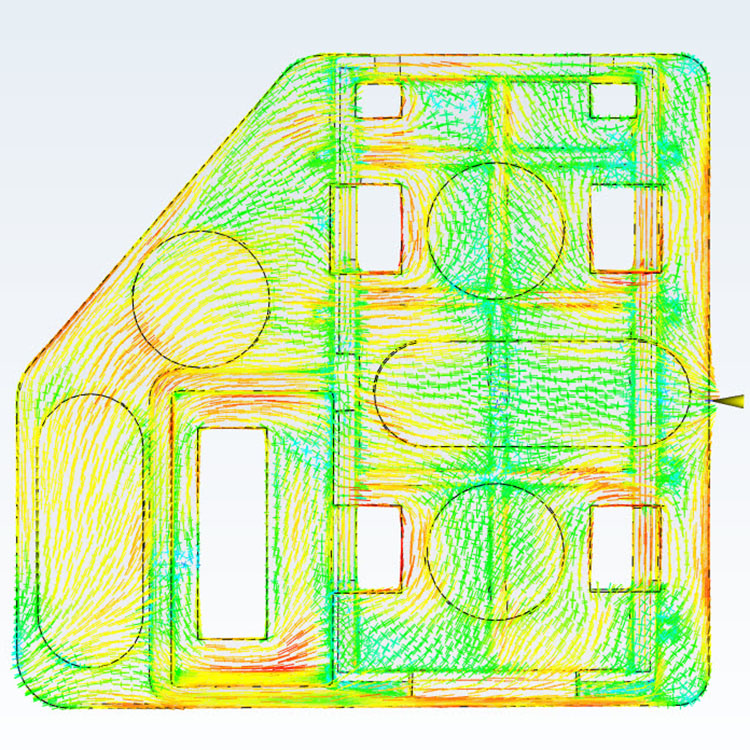
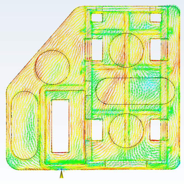
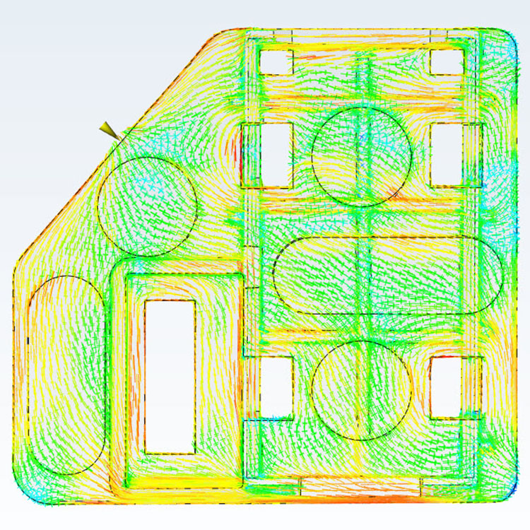
You can see how the direction of flow changes as we change gate locations. For glass/carbon-filled materials, the part will be stronger in the direction of flow. In other words, trying to bend a part with the bend perpendicular to the flow direction will be stronger than with it. You’ll notice though that the flow is mostly in the direction away from the gate, but the presence of varying features will disrupt the plastic flow and therefore can change the shrink.
Varying Wall Thickness
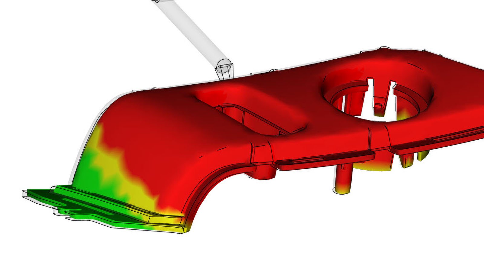
Attempting to have a uniform wall thickness when designing a molded part is one of the most critical design considerations. Having varying wall thickness contributes to differential cooling where areas of the part are cooling faster or slower compared to the others. This will cause a difference in shrink and possibly bad warping conditions. Attempting to have a uniform wall thickness is the best shot at avoiding this.
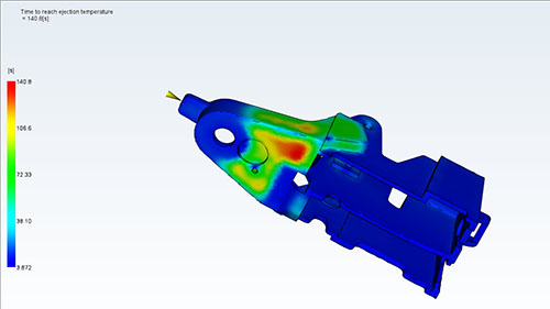
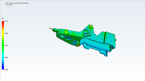
In the images below, you can see a hot spot created by having too thick of a wall section (shown in red). Most of the part (in blue) is cooling in less than ten seconds. Compared to the hot area that is taking over two minutes. The second image is after the part design has been cored out to make the wall thickness as even as possible. You can see that the cooling throughout the part is more consistent, and the cooling time is significantly lowered.
The Mold
You may be wondering since we are injecting plastic into a mold, how would a plastic part shrink if it essentially has nowhere to go? The simple answer is that the part is restrained from shrinking beyond the molding surfaces. However, it can shrink away from surfaces and will continue to shrink after it’s ejected from the mold. Imagine molding a plastic cup where there is a metal core inside the cup. Once the cavity is filled and the part begins to shrink, it’s shrinking onto the metal core but obviously cannot get smaller than the core. However, the cup could become shorter where the rim would shrink towards the bottom of the cup. Also, the outside of the cup may shrink towards the inside slightly, decreasing the wall thickness of the cup.
This is important in predicting warp. Not only does the part design matter, but so does how the mold is designed around the part. As the part cools in the mold, areas are restricted from shrinking, and stress can be created internally. Since plastic parts continue to cool after they are removed from the mold they will continue to shrink for several minutes after processing. During that time, the stresses may relax and cause warping conditions. It’s not uncommon to have cooling fixtures outside the mold to keep cycle time down but combat undesirable warping. These fixtures hold the part in key areas as it cools to maintain tolerances.
Gate Location and Processing
There is a high level of control when it comes to processing a molded part. We can change temperatures, flow rates, and times to attempt to combat warp. At the same time, these process changes can make it worse. Consider the packing and holding phase of the injection molding process. The end of the part may end up less dense than the area around the gate yielding different shrink rates from beginning to end of fill. Since part designs vary so much it may or may not be possible to combat these issues by changing the process or optimizing gate location.
The challenging component of part warp is not figuring out why the part warps. It is attempting to predict and prevent it from happening. As custom molders, we use both design best practices and software prediction to limit warping conditions. When we are starting a molding project, we want to consider the type the material, the part design, the mold design, and then develop a solid process to best predict and manage warping.
This post is part of our Designing for Injection Molding series. Check out more here.