One of the first considerations when designing a mold is selecting the parting line. Because the mold is divided into two halves, we need to decide where on the part one half of the mold will meet the other. For some applications, there’s an obvious choice, but in others, the the best option may not be so clear. We’re going to look at what to consider when selecting a parting line and what it means for part design.
We start off deciding which direction the mold will open relative to the molded part. This is known as the “line of draw” and will be a determining factor for how the rest of the mold is designed. When looking at a 3d model of a part, we’re looking at the potential need for actions like lifters and cams. In general, we only want to use the features if they are necessary. For more complicated part designs where cams and undercut’s cannot be avoided, we are deciding which part of the component will be machined into the tooling face and which should be a part of the action.
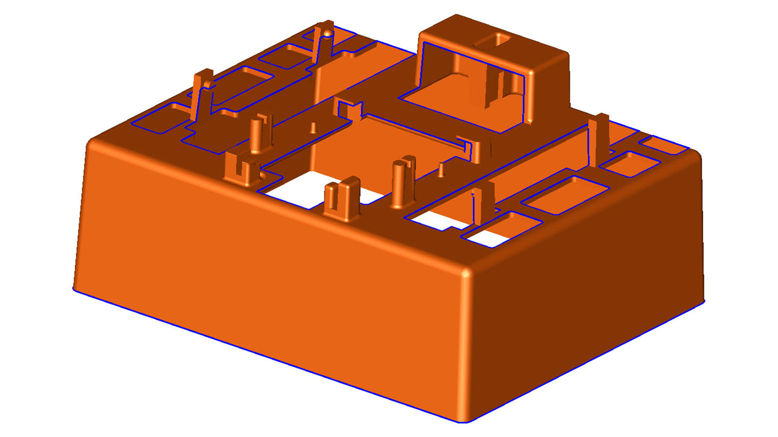
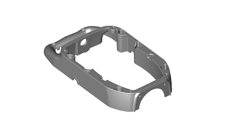 The image above is a part with several features. Most of which are perpendicular to the flattest sides of the part or vertical in the image. It makes the most sense then to make that direction the line of draw of the mold. The image below shows the line of draw.
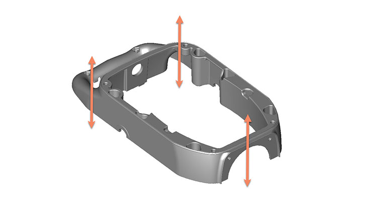
Looking closer at the model, there are three holes perpendicular to the line of draw. These are indicated in the image below.
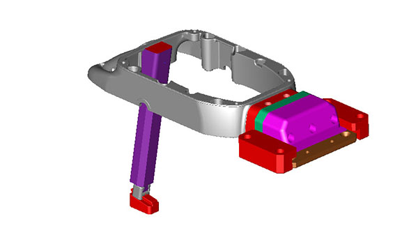
 The two smaller holes on the right side of the image are also inside of an arced ledge. For that aspect of the part, a cam action would be ideal. The other hole in the upper left of the image is trickier. Because the part design extends above that area (to the upper left of the image), a cam action is not possible. We also know that we will be gating the part from the middle area out, so a cam in the center of the part would not be feasible. In this case, a lifter assembly is the best choice. The image below shows both of these assemblies.
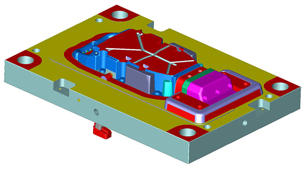
 Both of these components add to the complication of the parting line. The cam and lifter both need to seat properly against both halves of the mold to prevent flashing conditions. The image below shows the contact surfaces in red that create the parting line. In other words, these are the areas that need to seal off against other surfaces to create the part. You’ll notice some other contact points on the corners and around the cam body. These are locking in support areas explained more here.
Another consideration when selecting a parting line is what components are designed into a particular side of the mold. Since plastic shrinks as it cools, it will shrink onto surfaces. This is good and bad for designers and molders. We will use the shrinking to make sure the part stays on one side of the mold as it opens. At the same time, allowing the plastic to stick and shrink too hard will make the part eject hard or get stuck in the mold.
To combat this, we will draft or angle the walls of the molded part away from the parting line. The more draft we design into the part, the easier the part will be removed. More importantly, though, we want to make sure that the part is shrinking onto one side of the mold and away from the other. As you’d expect, this isn’t always cut and dry, but the trick is to have more features to shrink onto one side (possibly with less draft) than the other. We can also promote this using textures (or a lack of texture).
As mentioned earlier, molds are divided into an A and B half. The A half is going to be a show surface and will usually have a higher quality surface finish. The B-side is the opposite, where surface finish does not matter as much, and there may be marks from knockout pins. In part designs that lack significant features for pulling the part towards the B-side of the mold, we may be able to use a rougher surface finish.
Like many custom molding applications, the part and mold design are not always simple. The parting line is a simple concept but can be much more complicated to design and produce. Taking into consideration design features like cams and lifters can further complicate this. Once we’ve decided on the best parting line, there may be part design modifications required to allow for proper draft and surface finish to make the mold functions properly.
This post is part of our Designing for Injection Molding series. Check out more here.