As plastic cools, it shrinks and therefore shrinks onto molding surfaces. Because of this and a few other reasons, we draft (angle) the walls of the plastic part, so as the part is removed it breaks free from the molding surfaces easier and without dragging.
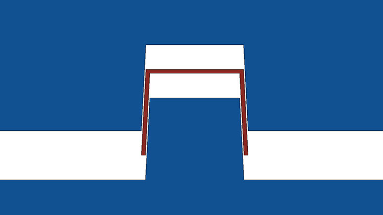
If you were researching “drafting an injection molded part” you may have stumbled upon an image like this.
While this shows the fundamentals of draft, applying it to part designs can become much more complicated. Factoring in features like advanced parting lines, cam actions, long draw lengths, and textures all make proper drafting more challenging. With that, we also need to factor in good design practices like uniform wall thickness. The images below are some applications that we have designed at Basilius.
This part required fitting to a spherical surface. The draft angles relative to the perpendicular surfaces vary from left to right in the image but stay consistent in the line of the draw of the mold (vertical in the image). Note that some of the surfaces may not look drafted but that because of perspective. The part also required some complicated undercuts that are detailed in this post.
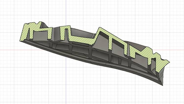
This is a colored draft analysis of a part with a contoured parting line and several shut off features. The draw line of the part was vertical in the image. As the parting line and shut off areas change, the draft relative to the line of draw stays consistent.
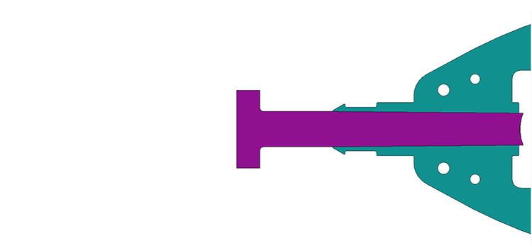
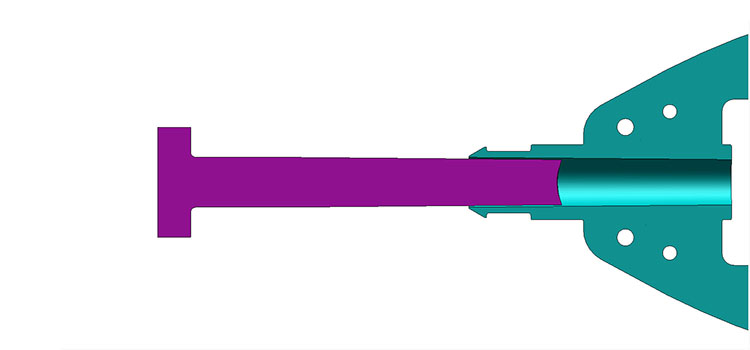
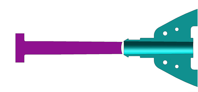
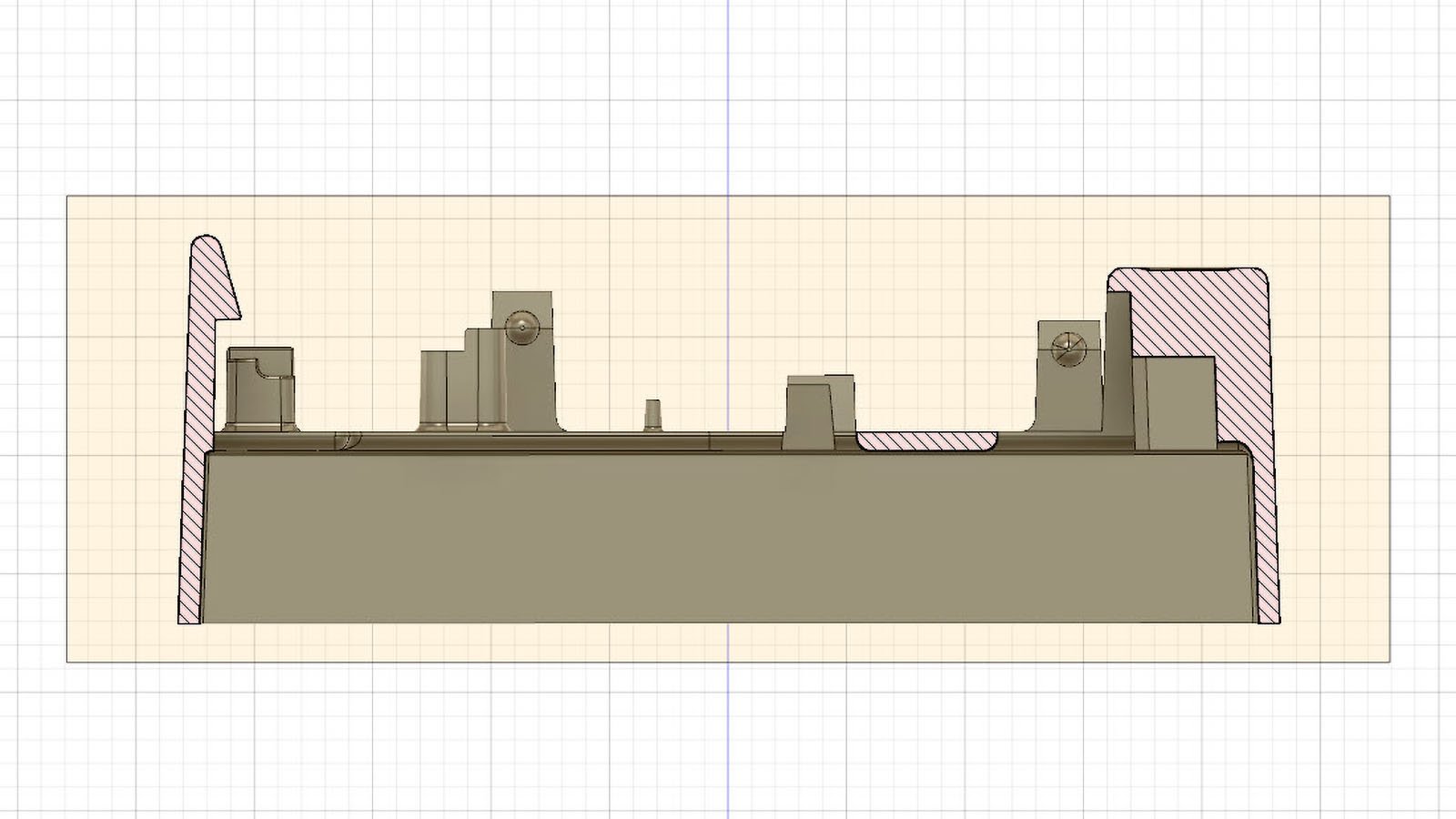
The images above are three stages of a long draw cam action (simplified). As features like part height and draw distance of cam actions get larger, the draft angle needs to increase. You can see in the difference between the first and second images that the cam (purple) is detached from the part completely. Although theoretically, any draft angle would accomplish this, plastic shrinks onto molding surfaces and is flexible to some degree. So having higher draft angles is advantageous.
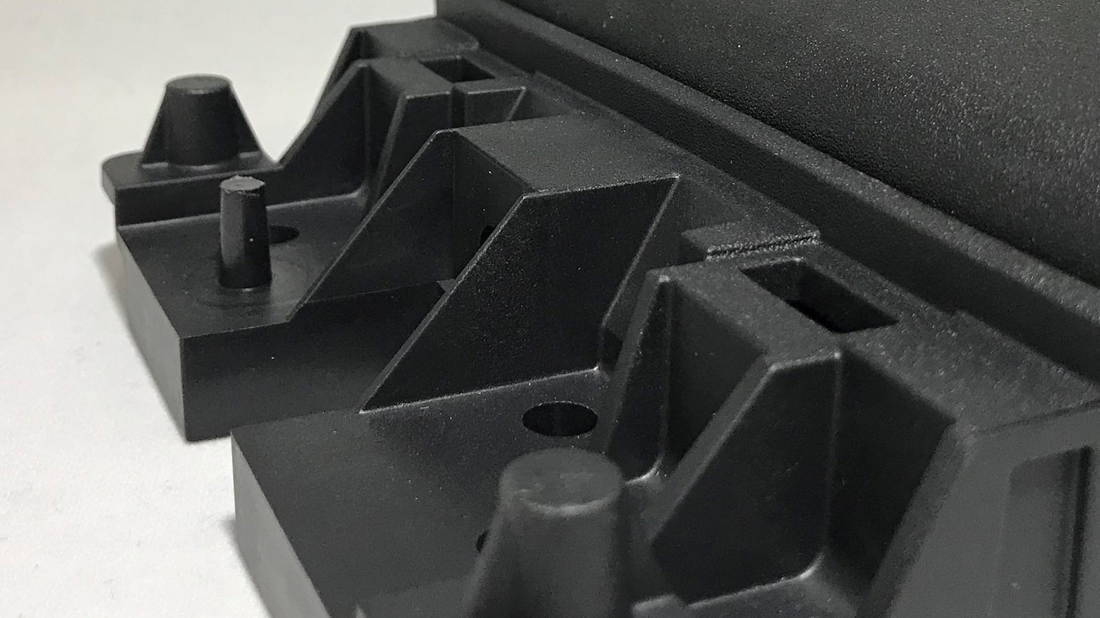
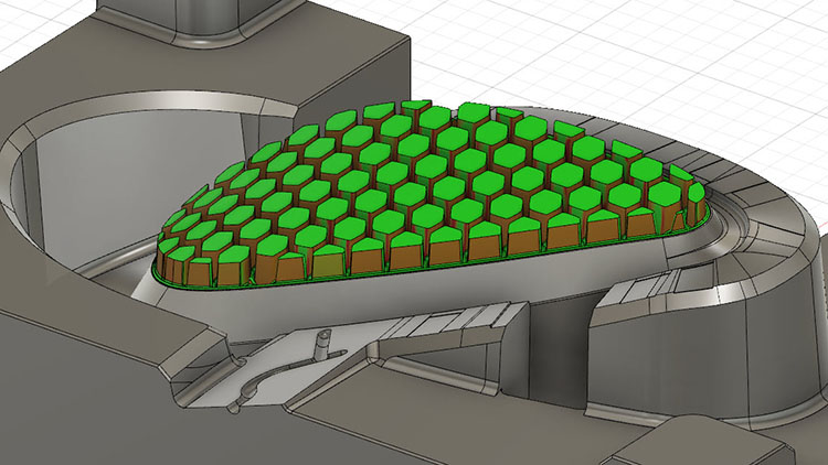
Looking closely at this image, you can see a textured surface. There are many different textures available for injection molded parts. Generally speaking, the more aggressive the texture, the more draft is required. Texturing molding surfaces is like having millions of tiny undercuts on the mold surface. Not drafting the walls to match the level of texture will cause drag marks or create difficulty ejecting.
Drafting your part designs is fundamental, but sometimes is a complicated aspect of designing for injection molding. Factoring in advanced parting lines, cam actions, long draw lengths, and textures all make proper drafting more challenging. At the same time, they are key to mold functionality and part quality.
This post is part of our Designing for Injection Molding series. Check out more here.