INJECTION MOLDING
Value-Added Services
Connecting design, tool building, and injection molding under one makes Basilius a turn key supplier. To further expand on those capabilities, we also offer value-added services. These include adhesive tape application, drilling and tapping, assembly, hot stamping, pad printing, and ultrasonic welding. Below, we dive into each service to help you understand the process and how it’s used in the industry.
Designing for injection molding
Your complete guide to injection molding design
Quicklinks
Full Guide
Adhesive Foam Tape Application
Two-sided adhesive foam tape is used in many industries as an alternative to mechanical fasteners. It applies quickly and creates a strong, permanent bond.
Anatomy of Foam Tape
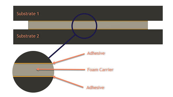
In Figure 1 below, you can see that two-sided foam tape has three laminated sections (with the release liner removed).
Different Grades for Different Projects
Even if you have never used two-sided foam tape, there’s a good chance you have interacted with some form of it. You will often find the tape used in consumer products, industrial goods, or construction. Each one of these applications use a different grade of tape to provide various material properties. To get a good overview of the different grades, check out this overview from 3M.
Forces
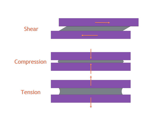
When starting a project, you’ll want to consider how the tape is going to interface between two components. You also want to consider what materials the tape is being applied to and what forces will be applied. When connecting two surfaces with two-sided tape, there will be at least one or, sometimes, a combination of all three of the following forces: shear, compression, and tension. See Figure 2 for examples of each force.
Each grade of tape will have a recommended load rating for these different forces. It is essential to reference the manufacturer’s website for those specifications. When in doubt on strength properties, we highly recommend adding more surface area to the tape. If your product starts failing in the field, the cost of brand damage and replacement could make the extra investment in tape seem small.
Surface Preparation
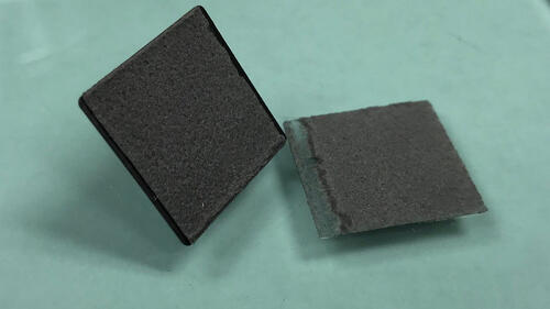
Note: Although these tapes are strong, if they fail, it will most likely be through the middle of the foam (cohesive failure). Cohesive failure means that the tape did not disconnect from each substrate; instead, it “tore” through the center foam section, leaving remnants of the tape on both sides of the part. Figure 3 shows an example of cohesive failure between glass and a plastic part. You can see the tape failed as expected during testing.
One of the advantages of using tape is the ability to make two contoured parts stick together. In order for this to work, the contour needs to match closely. The tape can absorb some variations is surface features, but without proper contact (wet out), the surfaces will not adhere properly and will eventually fail.
Figure 4 shows a part attached to a piece of glass. You can see that the contact area between the tape and glass in not ideal, as only half of the tape is in contact with the glass. This low wet out condition will reduce the strength of the connection and may eventually cause the connection to fail.
Tape Converters
The supply chain has a few layers to it that will help with your understanding of the tape and cost savings opportunities. Manufacturers, like 3M, produce all the various grades of two-sided tape in bulk. Typically, these are four-foot-wide rolls that are hundreds of feet long. Tape converters are the next layer in the supply chain. These businesses buy tape in bulk and cut (convert) the large rolls into whatever their customers need. The converters can produce just about any design to fit various applications.
Generally speaking, the more complicated the conversion process, the higher the cost. That is, a basic square of two-sided tape is probably going to be more cost-effective than an oddly shaped die-cut piece. However, because of the various types of tape and different conversion methods, there’s no hard rule as to what kind of tape or method is more or less cost-effective.
Drilling & Tapping
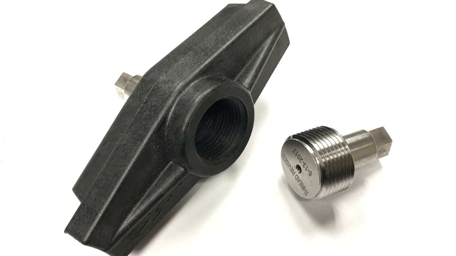
Figure 5 is an example of an injection molded part made with hand loads. The part (in black) has two opposing threads. The threads are created by loading the hand loads into the mold before the injection molding process. The part is then removed from the mold and the hand loads are unthreaded.
For some applications that have multiple small threads (for example), hand loads may not be feasible or cost-effective over time. Hand loads may not even be possible if threads are close together and take too long to unthread/reload into the mold.
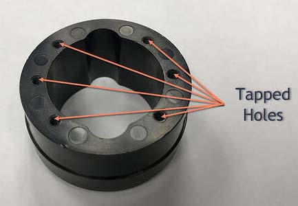
The part in Figure 6 requires six small taped holes. Because the annual volume was low in this case, investment in automatic tooling to generate threads could not be cost-justified. However, hand loads for each thread would slow the molding process and require a full-time operator. For this particular case, it was best to run the mold without an operator and tap the plastic using CNC equipment as a post-molding operation.
The cycle time for tapping the part in a CNC machine was faster than if the part was molded with an operator using hand loads. So, even though both operations require a machine operator, the post-molding process is more cost-effective because of the more efficient use of labor.
Assembly
If you product has several plastic (or other) components, there’s a good chance that “some assembly may be required.” If you’re a manufacturer, you’re most likely buying these plastic components and integrating them into your manufacturing processes. This may work well, but it’s worth considering how those plastic parts are manufactured and talking to molder about value-added opportunities. Allowing your molder to handle even simple assembly functions in line with their process may prove to be more cost-effective than doing it yourself.
For many injection molding operations, there is a full or part-time operator tending a molding machine. Machine operators may fulfill tasks like part separation, insert molding, or packaging in tandem with the molding machine. In some cases, when the operator finishes the task, they have to wait on the next molding cycle to complete. That lag time could be an opportunity for them to fulfill an additional task that you would otherwise be paying an additional operator at your facility to complete.
Imagine this scenario: Let’s say you have a product that gets packaged in a custom injection molded case (like a drill bit set). The case has a top and bottom (provided by your molder), which are connected by a hinge. Currently, you’re buying the top and bottom halves, and once received, you have a team member insert a metal pin through the hinge to complete the assembly. Quick and straightforward to achieve, but not necessarily the best use of labor. Not only are you allocating labor, but there may also be an opportunity cost to that team member’s time. After all, your product is in the case, not the case itself. So, obviously, it makes more sense to focus time and energy on your product.
The missed opportunity, in the case example, is that your molder may have a machine operator with enough time during the injection molding process to complete the assembly required. This could help significantly with overall cost savings. In addition, it may simplify your manufacturing process and free up a team member to focus on higher-value initiatives. You would no longer need to stock pins or pay someone to complete the assembly. You could simply order the case, add your product, and ship to your customers.
This is a straight forward example. The cost savings/efficiency opportunities will vary from project to project. The important take-away here is to talk with you molder about the entire process. You may find that there are opportunities to leverage each others’ capabilities to create a more cost-effective and efficient supply chain.
Hot Stamping
Hot stamping is a process used for generating graphics or lettering on plastic parts. Unlike ink or paint, the hot stamping process is relatively quick and does not require drying time. Hot stamping also allows you to change colors and designs with ease. Hot stamping uses a heated die that presses a special foil down onto a plastic part (substrate). The pressure and heat cause the foil to transfer onto the substrate so that when the die is lifted back off the substrate, the foil is left behind on the substrate.
The desired design or lettering can be created in one of two ways. Either the die or the plastic part has the design, and the opposite component is smooth. For example, a plastic part could have lettering raised off the surface of the part (molded in during manufacturing). In that case, the die would be smooth. Once the die is pressed onto the plastic part, the foil and die only contact the top areas of the lettering. The advantage of this method is that the plastic has a raised designed that is slightly easier to see.
In the opposite case, the die would have the design engraved on its surface, and the plastic part would be smooth. When pressed onto a smooth plastic surface, the design is pushed against the foil and part, transferring the design onto the plastic part. This method gives you the ability to change out the die and create different designs on the same plastic part, whereas in the previous case, whatever is already molded into the part is what can be hot stamped.
Hot stamping is a relatively fast process but requires specialized dies and fixturing. These specialized dies and fixtures add upfront costs at the beginning of a project, but the ongoing price can be reasonable, especially at higher volumes. As with many manufacturing processes, it’s possible (at higher volume) to add automation equipment/robotics to lower these prices.
Pad Printing
Pad printing is a process for applying ink-based graphics to various surfaces. Using this printing method gives you the ability to create multi-color, high-resolution images on 3D contours. Compared to other printing methods, this unique ability makes pad printing particularly advantageous to injection molded components. Since many molded parts are not flat, pad printing provides a cost-effective, simple way to add branding and other designs to your injection molded parts.
The process begins with the required design being etched into the surface of a flat plate. The etching creates a concave area on the plate. Next, an ink cup is pushed across the surface of the plate, which allows ink to sit in the etching. A silicone transfer pad is then pushed into the etching, transferring the ink to the pad. Finally, the pad is pushed onto the component to transfer the ink.
If you need to create multi-color graphics, multi-station pad printing equipment will transfer each color onto the same location of a component. The layering of various colors can create detailed images and logos relatively quickly.
Ultrasonic Welding & Heat Staking
How It Works
Joint Design
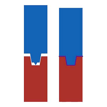
The connection point of the two materials is critical to the performance of the ultrasonically welded joint. At the joint, there needs to be a feature called an energy director, which is a small pointed ridge molded into one of the surfaces. The ridge is typically a triangular shape with the point facing toward the opposing surface. During the welding process, the energy director melts into the other surface to secure a solid bond.
From a design perspective, the pointed ridge should be between a sixty and ninety-degree angle and have a height ranging from .008 inches to .025 inches. Designs will, of course, vary based on the application requirements and materials. Figures 7-10 show some examples of joint designs.


Cost
Designing for injection molding
Your complete guide to injection molding design