Several years ago, SPI (Society of Plastics Industry) introduced mold building classifications to help standardize molding requirements based on the number cycles required. Although all mold builders do not use these classifications, they are a good starting point for creating expectations of performance and longevity.
Note: These standards do not imply a level of craftsmanship or a guarantee of performance, but instead, refer to the mold materials used and mold features to incorporate.
Class 101
- Cycles: one million or more
- Built for extremely high production, this is generally the highest priced mold and is made
with only the highest quality materials. - Detailed mold design required
- Mold base to be a minimum hardness of 280BHN
- Molding surfaces (cavities and cores) must be hardened to a minimum of 48 R/C
range. All other details should also be hardened tool steels. - Steels moving against one another should be dissimilar and have a hardness
differential of at least 4 Rockwell. - Ejection should be guided.
- Slides must have wear plates.
- Temperature control provisions to be in cavities, cores, and slides wherever
possible - It is recommended that plates and inserts containing cooling channels be of a
corrosive resistant material or treated to prevent corrosion. (Corrosion in the
cooling channels decreases cooling efficiency, thus degrading the part quality and
increasing the cycle time).
Below you will find a more detailed explanation of the major classifications listed for class 101 molds. For more information on other mold classes check out this post.
Detailed Mold Design
Every mold requires some level of design. These designs are created in 3D by engineers using computer-aided design (CAD) software. Once complete, the 3D design file is utilized throughout the mold build process. For CNC machining, technicians will load the 3D data into computer-aided manufacturing (CAM) software to program machining equipment.
Mold designs used to be drawn by hand, and a series of prints would be used by a machinist to build the mold. Engineers are no longer creating prints by hand, but they will create prints from 3D data in CAD software. The prints will detail tolerances, materials, assembly notes, water flow direction, etc.—information that may not be readily apparent when looking at 3D data. More importantly, this information may not transfer automatically from different CAD programs. It takes time to make an accurate print that leaves nothing up for interpretation.
With increasing pressure on mold builders to decrease leads times, it became apparent that unless making detailed drawings was necessary, they could skip the extra step of making prints. A good example of this is low volume or prototype molds. These molds are simple enough that 3D data and material specifications are good enough to build the mold. Since these molds will not see a production environment nor require replacement components, the print becomes unnecessary.
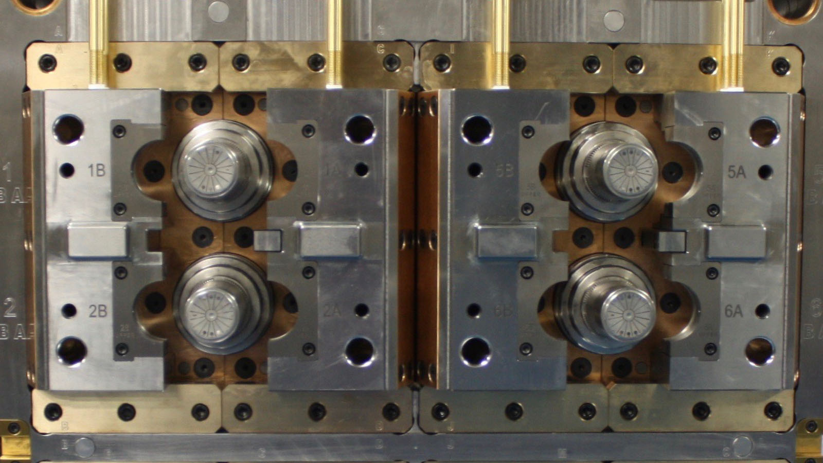
Mold Base & Tooling Hardness
Different components of the mold will have different hardness levels. The hardness of a material is its ability to resist indentation, scratching, and general wear. In the tooling industry, both Brinell Hardness (BH) and Rockwell Hardness (RH) are used to reference material hardness. In the class 101 specifications, you’ll see a hardness spec for the mold base and for the tooling.
The mold base is the support structure of the mold. This structure needs to resist clamp force from the molding machine as well as plastic pressure generated by the injection molding process. The class 101 mold specification for mold bases requires them to be at least 280 BHN. For perspective, wood hardness is less than 10 BH, mild steel is about 120 BH, and hardened tool steel is over 600 BH. The class 101 specification means that the steel used on the mold base is stronger than typical steel. Its higher strength means it will resist damage and the constant stresses created by the molding process, as well as, protect the mold when it needs to be disassembled for maintenance or moved. In addition, over time, molds get disassembled for maintenance and moved around a lot. Tooling inserts are specified to be 48 Rockwell or higher. Even though Rockwell is a different scale than Brinell, the same basic principles are applied.
Since the tooling surfaces come into contact with the plastic flow, they are more prone to wear over time. Tool wear, even on hardened tooling, can be accelerated by the type of plastic as well. Materials with high levels of glass fibers (greater than 10-20%) will wear out molding surfaces much faster than common materials like polypropylene.
Dissimilar Hardness
The two halves of the tooling interlock and seal together to create the full part form inside the mold. The two halves will be made of different materials with different hardness for each half. Having dissimilar materials and hardness in each half ensures that surfaces do not bind against each other over time. When you are expecting a mold to last well over a million cycles, these details are especially important. Once two surfaces begin to bind against each other, damage can occur quickly. When binding is immanent, you will begin to see drag marks, and eventually, the surfaces will become rough. If the roughness gets bad enough, the components can completely bind together and lock up, requiring replacement.
Guided Ejection
The ejection system of the mold is a mechanism for removing the plastic part from the mold after it has cooled. In the most simple applications, the ejection system consists of two plates that hold a series of ejector pins. The molding machine is connected to the plates and can cycle them forward and backward to eject the molded parts from the mold.
In class 101 molds, the ejection system is guided by a set of pins and bushings. This guidance ensures that the weight of the ejection system (plates, pins, and other components) are supported and can actuate freely. Without guidance, the ejection system will hang from the pin arrangement. This sounds like an engineering disaster, but unsupported ejection systems can actually last a long time—they are just not optimal for getting the maximum life from the ejection system .
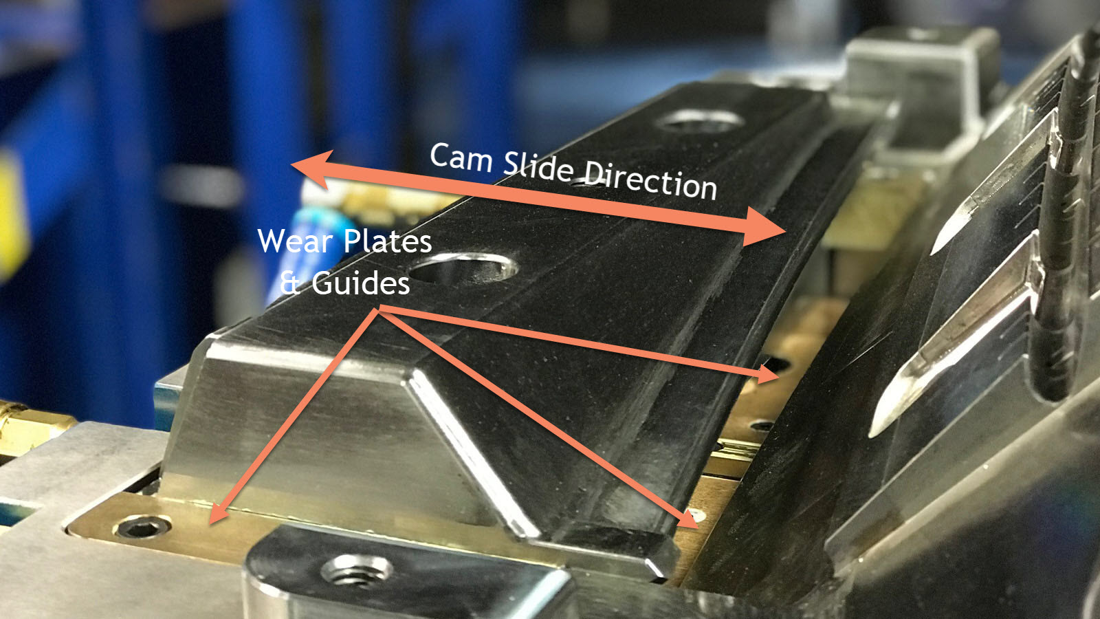
Wear Plates
To meet the longevity requirements of class 101 molds, cam actions are guided by wear plates. The cam body is surrounded by wear plates that not only guide it, but also provide a lubricated surface for it to move along. Wear plates are, of course, designed to wear, but they can be easily replaced. However, with proper lubrication, they can last hundreds of thousands of cycles. If wear plates are not used, tooling surfaces can wear out, requiring complete replacement or welding and reworking—a much more difficult process.
Temperature Control
Nearly every mold has some form of temperature control system (the exception is quick turnaround prototypes). Temperature control usually consists of some assortment of holes drilled through the tooling blocks to help move temperature-controlled water (or oil) through the mold. Since part of the mold’s job is to remove heat from molten plastic, how well these channels are designed directly relates to the performance of the mold. Cooling the plastic in the mold is the longest part of the molding process, so even the smallest reduction in cooling time can generate significant cost savings over time. For longevity, the cooling channels should have the means to resist rust and mineral build up. Rust and build-up will slowly reduce the efficiency of the cooling system. To combat this, class 101 molds will use either a heat treatable stainless steel or have the cooling channels coated with nickel or other specialized coatings.