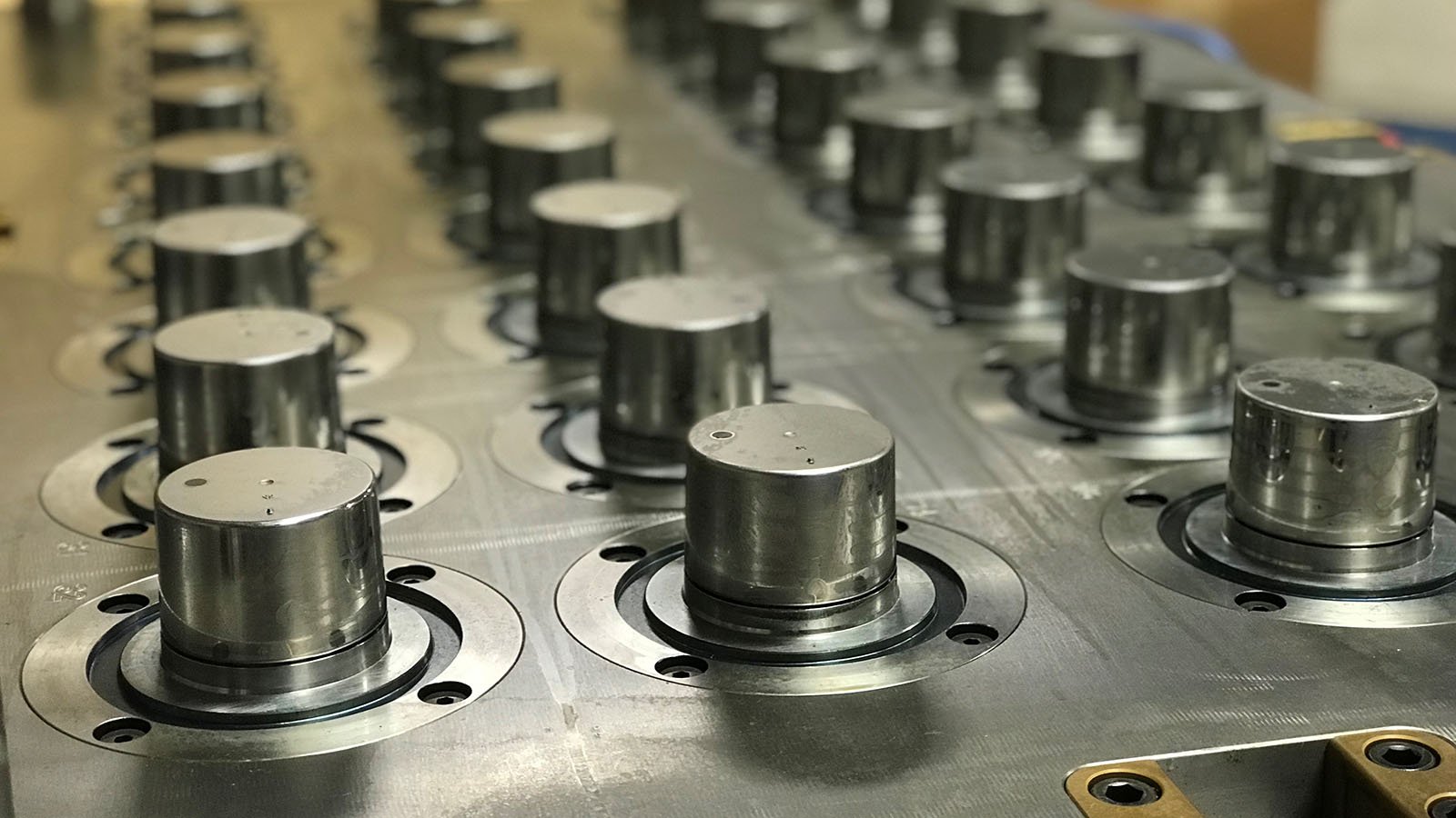
This project was built for an injection molding company in the capping industry. The main concerns with parts like these are cycle time and the ability to produce an extremely high volume of parts consistently and reliably. Being able to do this comes down to intelligent tool design and a quality build.
Getting into high volume applications like this requires additional considerations in the design process. For example, using a cold runner system to feed 32 cavities is not economical as it can add injection time, increase plastic pressures, add to take out time, increase the overall size of the mold, and several other defects. For this part, there were several advantages to utilizing a 32 drop valve gated hot runner system.
-
Having a hot drop feeding each part eliminates the use of regrind and the management of runner systems after the molding process.
-
Feeding the parts directly eliminates the pressure losses associated with a cold runner system.
-
The valve gate system in the hot runner gives the process engineer direct control of gate freeze time.
-
Saving on cooling time by eliminating the thick wall section created by the runner system.
-
Increased dimensional consistency.
The next design consideration is optimizing cooling channels to remove heat as quickly and efficiently as possible. Several factors can dramatically affect the ability to remove heat from the plastic with the largest one bring wall thickness. For high volume applications, the goal is to have as thin of a wall section as possible without affecting the part functionality and moldability. Using tools such as Moldflow, we can consider the part design’s influence on the process.
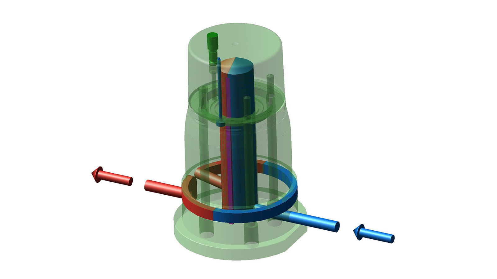
Beyond wall thickness, designing effective cooling and material selection can have a large impact on cooling time. In the image below, you can see one cavity and the path of the cooling system. Water enters from one side of the core insert, travels up a large channel directed by a baffle, back down the same channel, and then out and around. For reference, the water flow is drawn in 3D. The blue colored area represents the first half, and the red colored area represents the second half. Each cavity is fed by a series of water lines machined into various plates of the mold.
Cycle time is such a major factor in the molding operation, making sure the parts eject off quickly and easily is critical. The pictures below (drawing simplified) shows how the ejection system works. The use of a stripper ring system creates a balanced and even mechanism for removing the part, while also helping to remove an under-cut feature in the plastic part.

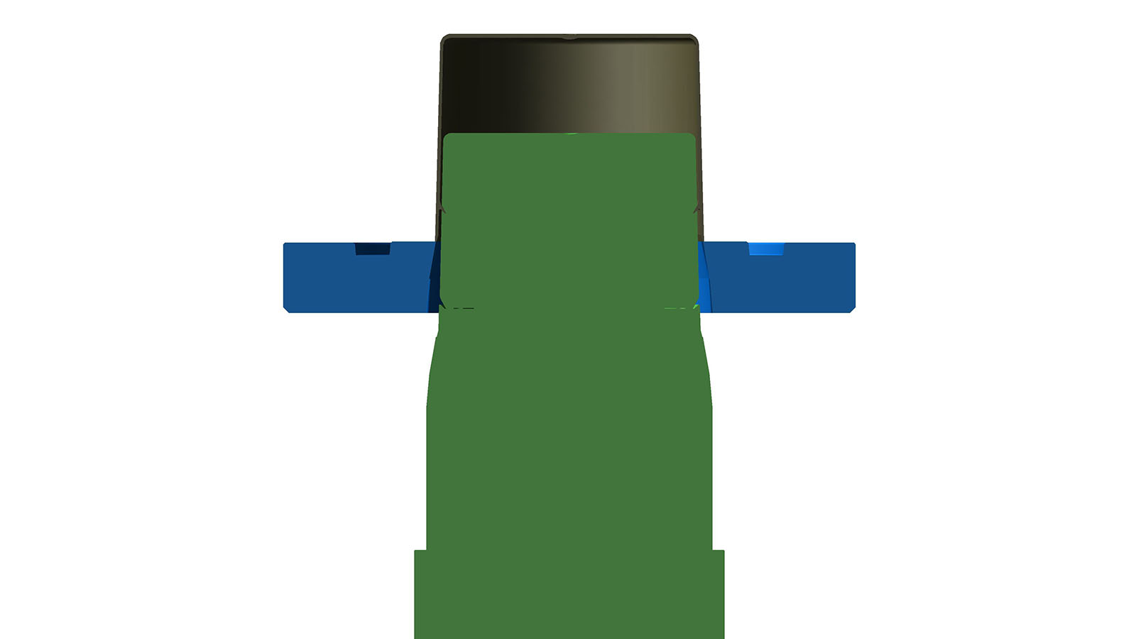
To assist further with ejecting the part, we added an air poppet on the top of the coring. Air poppets are essentially small valves that open when air pressure is applied, to allow air to flow to the desired location in the cavity. Without the air poppet, a vacuum condition would be created between the part and the coring. This vacuum condition would potentially damage the part during ejection. The injection molding machine controls this system, via an air solenoid.
As you can see, the application and the goals of our customer are essential in the design process. We were excited to take this project on at Basilius. We were able to look at the overall program and work with our customer to design and build a mold to meet their expectations.