featured articles
selected by our team
At Basilius we are here to help. Our blog is filled with informative articles and industry knowledge. Articles are added on a regular basis so check back to get the latest information from Basilius.
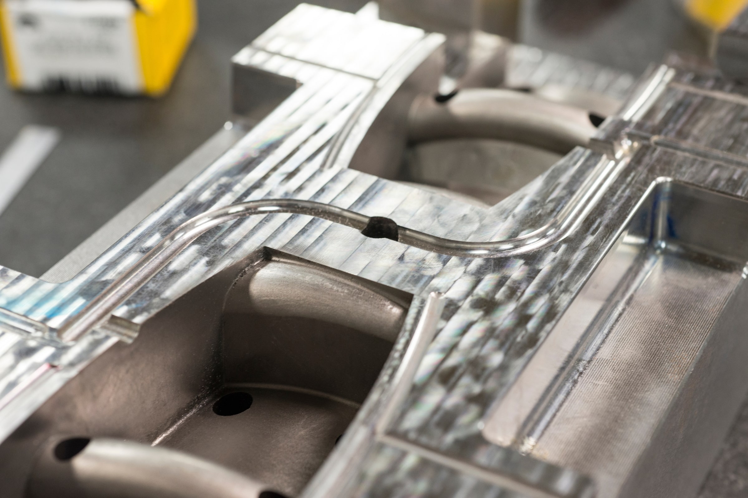
Exploring Aluminum Injection Molds
Choosing the right material for your injection mold matters. Today we explore
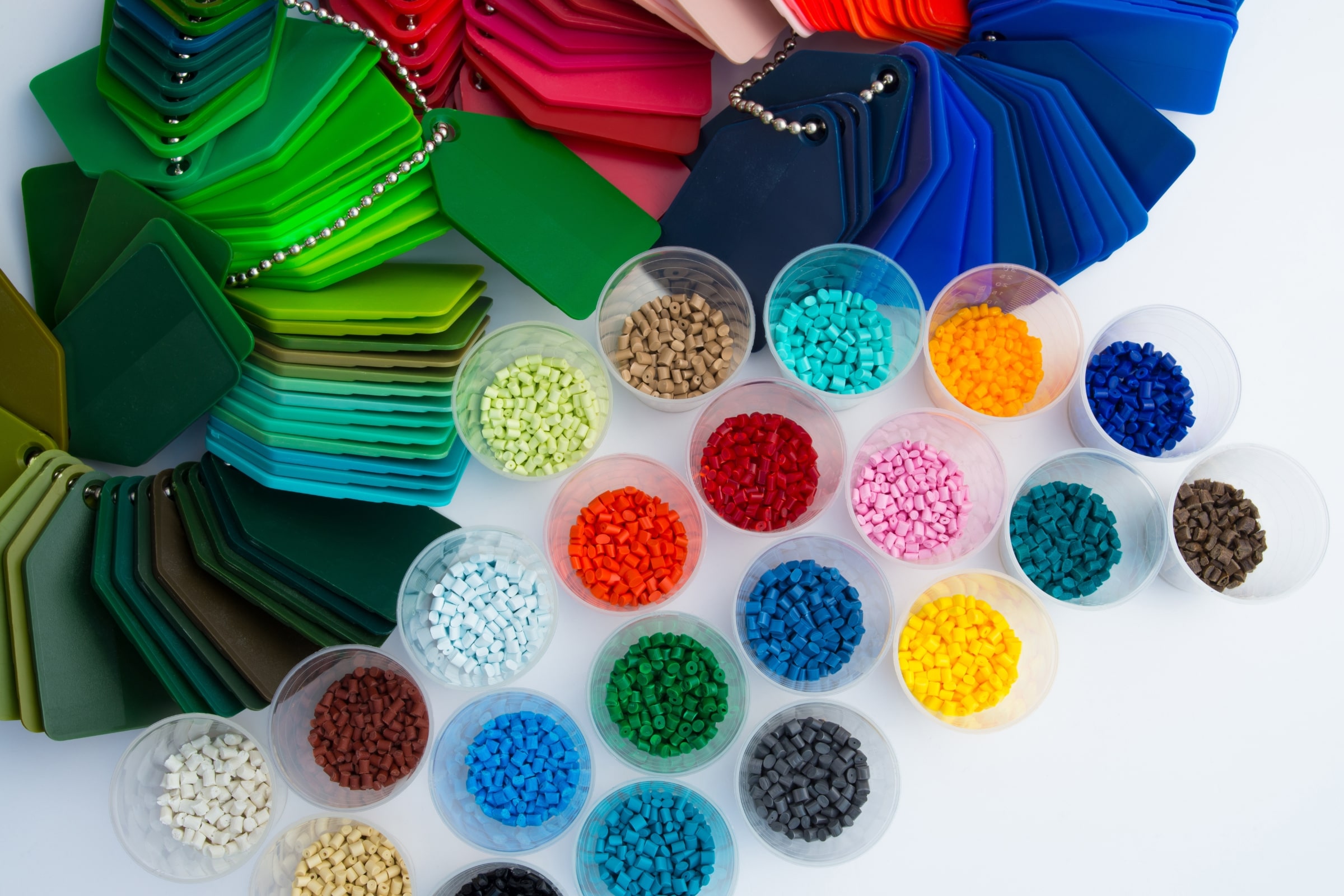
The Complete Guide to Injection Molding Materials
Which injection molding materials are best for your project? We discuss the
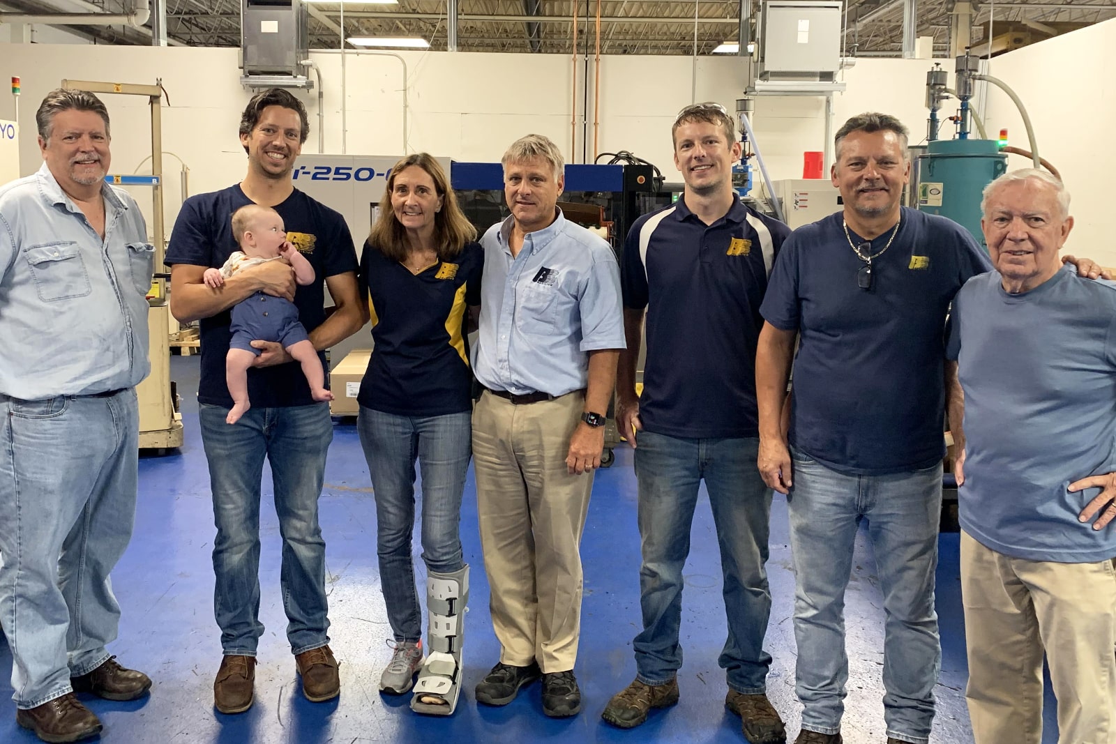
Thriving into the 4th Generation
It’s been stated by many that a very small percentage of family

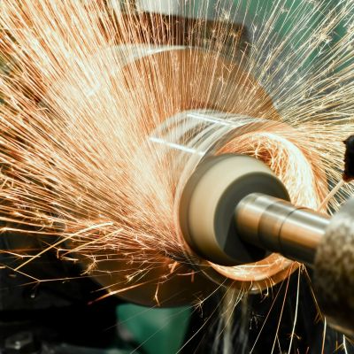
Surface finishing plays an important role in the manufacturing process. Let’s discuss popular techniques and applications.

This is how Basilius is accomplishing 100% machine vision inspection at the press.
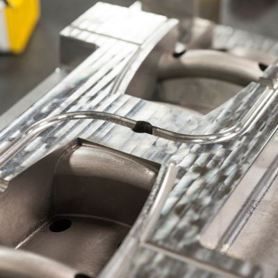
Choosing the right material for your injection mold matters. Today we explore the benefits and challenges of utilizing aluminum injection molds.
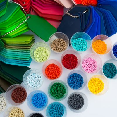
Which injection molding materials are best for your project? We discuss the pros and cons of the various materials available.
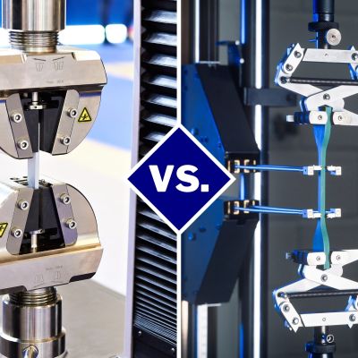
Understanding tensile strength vs yield strength is critical in your material selection process. This guide covers both topics at length.
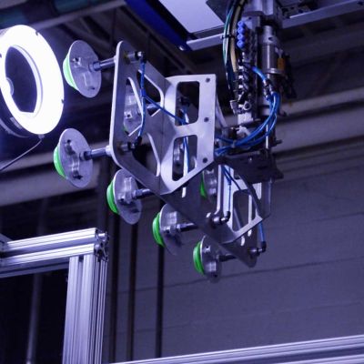
See how Basilius is using robotics to support high volume injection molding applications
There are several types of injection molding gate designs. He we cover the designs, it’s purpose, and benefits during in the injection molding process.
If you’re looking to save money with a more energy efficient injection molding process, we have the 7 steps you need to look into right away. We’ll also cover the benefits of energy savings and why it all matters.

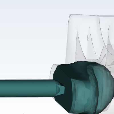
This part is a molded filter has .03 inch openings. Basilius is able to achieve optimum quality using an integrated machine vision system
helpful resources
to get the most out of your project
Our experiences have shaped who we are as a company and we are happy to share our knowledge and expertise with you.