As CNC machined components become more complicated so does the equipment and tools to produce it. Over the last several decades of providing CNC machining services, we’ve found some simple design tricks we’d like to share. They can make parts function better, machine easier, and may even provide some cost savings.
Eliminating a Corner Radius
CNC milling operation automatically creates a radius on vertical inside corners. If your assembly requires a sharp corner, there are a few options available. The lower two corners in the image below show the corners drilled out. The diameter of the hole is large enough that the vertical and horizontal walls are completely straight. The top two corners use a design feature that accomplishes a sharp corner with a slightly different design.
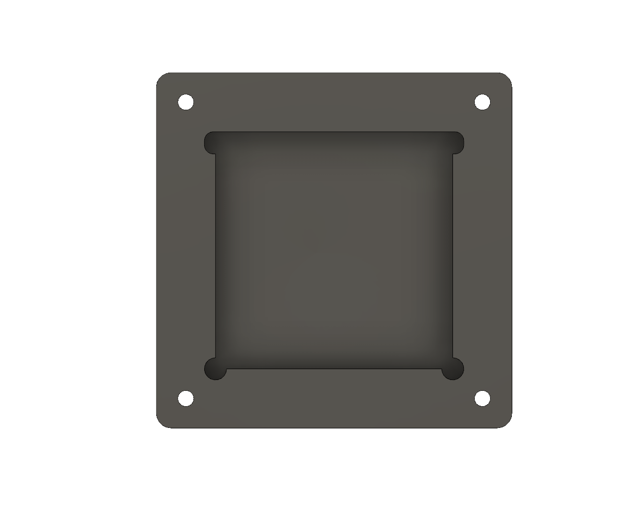
These features are designed around allowing a mating component to have a sharp corner. That is, something with sharp corners needs to fit into the pocket in the image above. If the mating component cannot be modified and the above design features are no possible, the corners can be EDM’d to a much smaller radius. As mentioned previously, this is an additional cost and set up that should be avoided.
Turning Threads
For CNC turning threads, it is common to have the threads end into a face. The challenge is that when CNC turning threads, the tooling inserts cannot produce a thread that ends completely against a face. Meaning that a mating component could possibly bind and stop against the end of a thread rather than against the face. If the mating component cannot be modified, you can undercut the end of the thread to the root diameter of the thread (see image below).
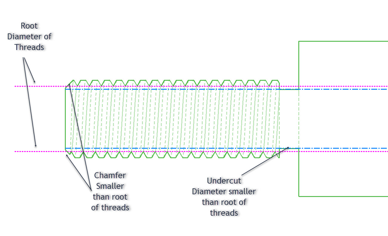
When designing threads, it is also important to add a proper lead into the thread by using a simple chamfer (shown above). The diameter of the chamfer should be smaller than the root diameter of the thread. This will prevent a burr; it also provides a nice lead-in for mating parts.
Zero Inside Radius on a Turned Component
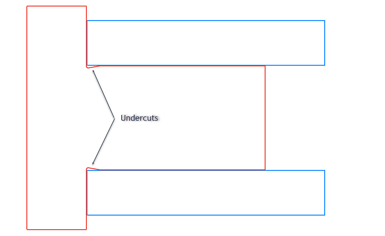
Most lathe tooling has a radius for performance and chip removal. The tool radius automatically creates a fillet on inside corners. The radius may work against you if you need a sharp corner for a mating component. You can design in a small undercut to make sure a mating component with a sharp corner can fully engage into the CNC turned part. Below is a common example of a pin (outlined in red) and a bushing (outlined in blue). The undercut on the pin allows the bushing to fully engage into the face of the pin without interference.
Non-Standard Fillets and Radii
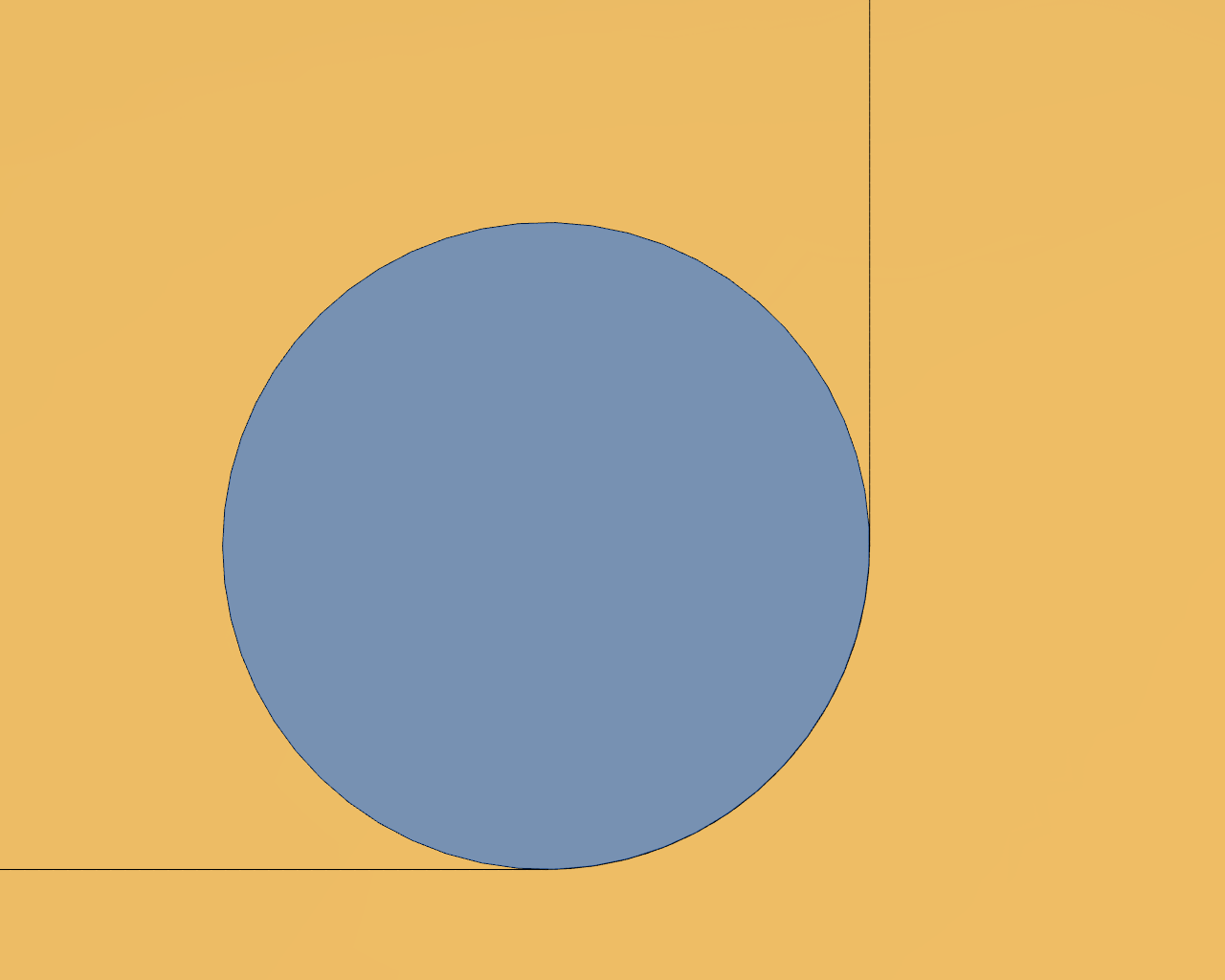
When designing radii on a part, it is best practice to make the radius a non-standard value. That is, instead of having a .250 corner radius, make it slightly over (.260). Doing this ensures that CAM software generates the radius with cutting equipment, rather than allowing a tool to engage fully in a corner. In the images below you can see a simplified 1/2 inch diameter tooling insert (blue) and a component (yellow) with two slightly different corner radii. In the first image, the tooling will most likely hit the corner and fully engage, which may cause vibration, tooling damage, bad surface finish, or may even cut the corner oversize.
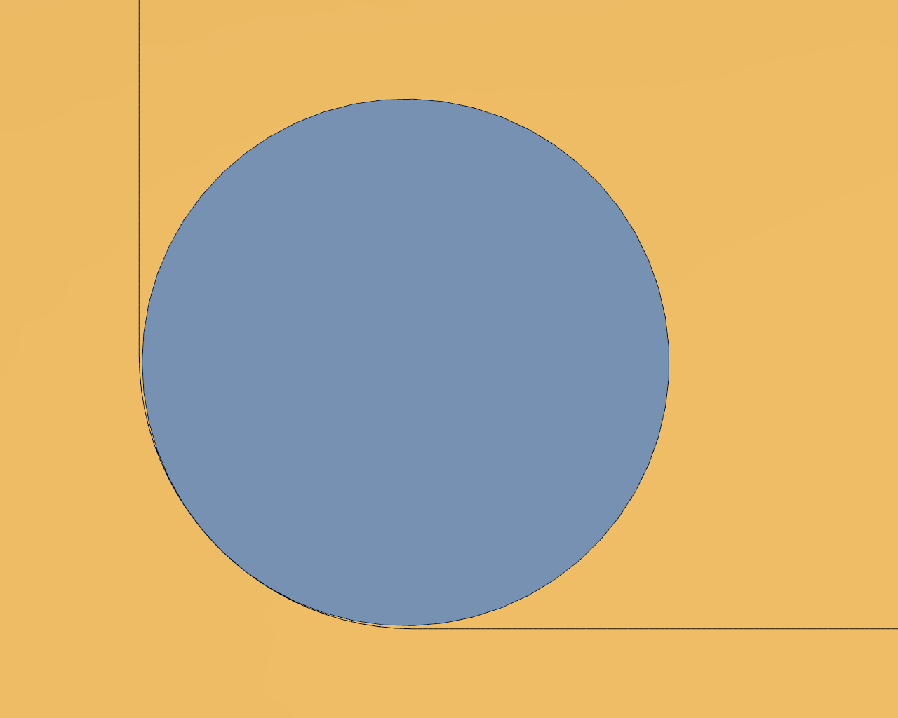
In the image below, you can see the same type of situation with a slightly larger corner radius (.260). The difference is almost unnoticeable but is enough to prevent a chattering condition. To produce an exact .250 radius without chattering, a machine operator will likely use a smaller tooling insert. If the smaller tooling is only used for finishing corners, it’s adding machine time that could have otherwise been avoided.
Think Big
In general, smaller features take more time to produce. For example, since a CNC milled pocket will generate an inside radius, it is better to have a radius at .260 than .100. In the example part shown below, the corner radii are highlighted in blue.
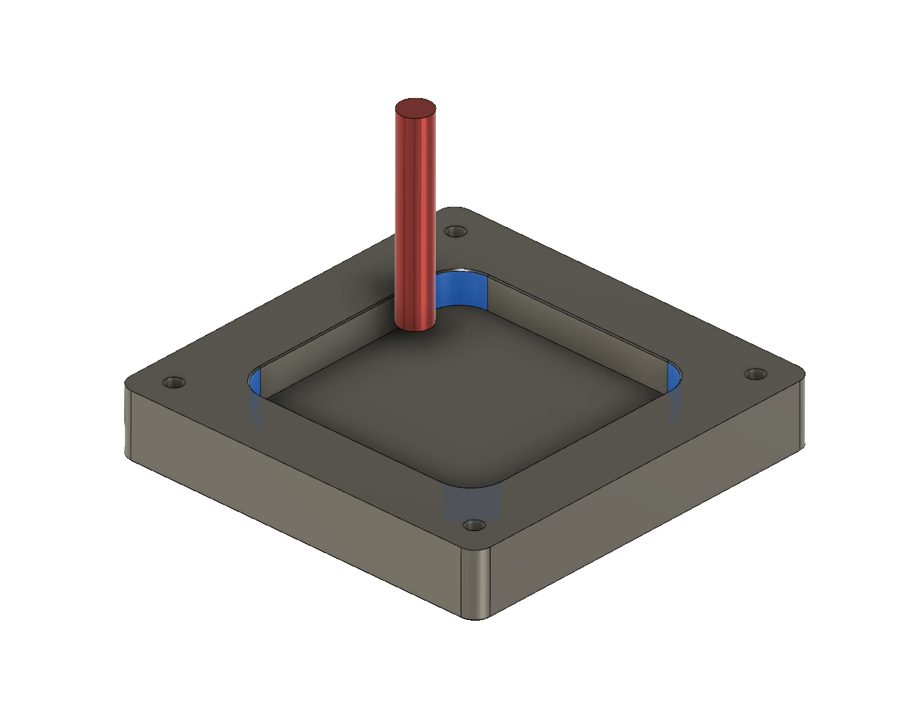
The corner radius is .260 and therefore, can be produced by a half inch mill. That same tooling bit would likely be able to cut this entire part as well. If these radii were reduced to .135 , a 3/16 mill would be largest diameter tool able to produce the radius. The smaller tooling may not serve much of a purpose beyond cutting the smaller radius. Therefore, the smaller radius would require the setup of another tool, a tool change, and additional programming.
Keep in mind that design features like these are relative to the part design as a whole. If the part is small, then small features are unavoidable. The basic premise is that having lots of different design features that require several different types of tooling should be avoided when possible. It is also advantageous to keep sizes consistent throughout the part design.
Check out this page for more information on designing for CNC Machining.